Transcription of Veracity White Paper 002 - PoE Explained
1 Veracity White Paper 002:PoE ExplainedIntroductionSince its standardisation in 2003, power over ethernet (PoE) has found widespread application in markets such as VoIP telephony, wireless LANs, IP video security and access control. As discussed in Veracity 's earlier article, power Without the Struggle, its benefits as a power delivery method include drastically lower installation and maintenance costs, and its technology offers a supply that is reliable, safe, efficient and robust, while being as simple as possible to gives network installers control over the power distribution to their equipment, however for many this is not their fort : while the concepts behind PoE are straightforward in absolute terms compared to the complexities of other IT technology, the fundamentals of electrical power and its delivery are new territory to a significant proportion of White Paper , therefore, intends not only to serve as a reference to those technical features of PoE that are relevant to users of network equipment, but also to provide further explanation of the basic principles behind the technology, so that these features may be understood well enough to enable the effective design, installation and troubleshooting of PoE-enabled and 5 Cable and power Plus and Custom 11 December 1 of 14 Concepts and TerminologyPower over ethernet is defined across a single network link, and so the three basic components of a PoE connection are.
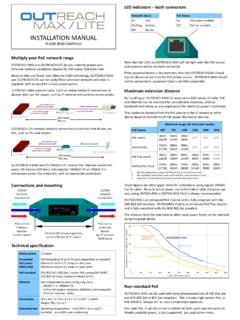
2 The equipment that delivers power to the cable (often referred to as a PSE, which stands for power sourcing equipment) The device which receives its power from the cable (also known as a powered device, or PD) The cable itselfTypical PDs include IP cameras, wireless access points (APs), etc., and the PSE would normally be a PoE-enabled network switch or a midspan power injector, patched in to add PoE capability to a non-PoE network switch channel or similar. These two configurations are shown in figure 1 1a. A PoE network switch can deliver power to a PD, such as an IP camera, over its data cableFigure 1b. A midspan PSE can be used to add PoE capability to standard network switch channelsThe terms PSE, PD and midspan are defined in the current IEEE specification for PoE, , which is part of the set of standards that define Ethernet1.
3 Nearly all devices described as incorporating PoE comply with this standard (although the manufacturers' literature should always be consulted).So that PoE can coexist with existing ethernet technology, PDs must display a signature to advertise that they can accept PoE, and optionally a power class, to indicate how much power they require. The PSE detects these before it connects power to the cable, in order to protect incompatible devices. Signature detection and power classification will be described in more detail in later is also designed to operate over standard network cable: Cat 3, Cat 5, Cat 5e or Cat 6 (often collectively referred to as Cat 5), using conventional RJ452 Technically PSE, PD and Midspan refer only to the power circuits of the equipment used, but they are commonly used to refer to the equipment itself2 Often (and more correctly) referred to as 8P8C connectorsVersion 11 December 2 of 14 DATAPOWERPOE SWITCHIP CAMERADATAPOWERMIDSPANIP CAMERASWITCH Electrical PowerBefore delving further into the details of PoE itself however, it is worth covering some of the fundamental concepts behind electrical power transmission, in general terms, as for many people an introduction or refresher in this area will lift one of the barriers to understanding 2.
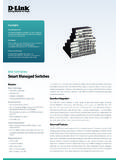
4 power being transferred over an electrical cable to a light bulbFigure 2 shows a common, simple example of electrical power being transferred over a long cable. The configuration forms an electrical circuit with properties that can be defined as follows: Voltage is measured between any two points in a circuit: it can be thought of as the force available to cause electricity to flow. Current, measured in amps, describes the rate of flow of electricity around the circuit. Its value is the same at every point in the loop shown. power is the rate at which energy is transferred, and is measured in watts. Electrical devices may convert this energy into different forms light, motion, etc. - but in most cases it ends up as electrical power being delivered to a device or part of a circuit can be calculated by multiplying the voltage measured across it by the current flowing.
5 For example, if the voltage across the lamp in the illustration, measured at point B, is 115 volts, and the current flowing around the circuit is amps, then the amount of electrical power being converted into heat and light by the lamp is equal to 115 x = 92 can also be seen that some of the power delivered to the circuit is lost as heat in the cable. This means that: The total power that must be drawn from the mains supply is more than that required by the lamp. In fact this can as much as double the power requirement of the circuit. There is a voltage drop across the cable. In other words, the voltage across the lamp at point B is lower than the voltage delivered at the mains socket, point 11 December 3 of 14 ABHEATELECTRICAL POWERCURRENTVOLTAGEHEAT+LIGHTThis power loss and voltage drop is caused by the cable's resistance.
6 Resistance is proportional to length and reduces with wire thickness, so the longer a cable is, or the lighter its gauge, the greater the power loss and voltage drop across it. In the example, the voltage at point A may be 120 volts (enough for the lamp to draw its rated 100 watts) but the resistance of the long cable causes 5 volts to be dropped along the way to point losses also increase as the current flowing through the conductor increases, which means it is more efficient to transfer electrical power at a higher voltage, as the current necessary to deliver the same power will be lower, so less power is lost in the cable. This is the reason that power grid transmission lines operate at such high voltages. Cat 5 Cable and power TransmissionThe principles of carrying electrical power over Cat 5 are no different to those of other power distribution systems, such as the AC mains wiring in the previous example, but as the power is being transferred over light-duty cable for long distances, the effects of the power loss and voltage drop become significant.
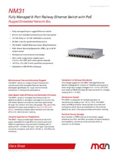
7 (The amount of power that is lost as heat in the cable is detailed in the next section).The arrangement and connection to the cabling used for PoE also differ slightly from conventional power wiring, in order to work around the existing standard for ethernet data. Cat 5 network cables contain a bundle of eight wires, arranged as four twisted pairs3 as shown in figure 3. In the most common type of ethernet , 100 BASE-T or Fast Ethernet4, only two of the four pairs are used to carry data; each pair carrying a signal in one direction. These are known as the data pairs, and the remaining two are unused and are referred to as the spare Twisting together the two wires used for a signal greatly reduces the amount of interference the wires pick up or emit4 Specifically 100 BASE-TX, in full-duplex modeVersion 11 December 4 of 14 Figure 3.
8 PoE power transmission using the data pairs of Cat5 cableTRANSFORMERSDATAPSE( PoE Network Switch)PD( IP Camera)CABLE( Cat 5E)BRIDGESPOWERPOWERDATAA lthough each data signal can be carried within a single pair, PoE treats each pair of wires as a single conductor (a reason for this is that using both wires halves the overall resistance). As electrical current must flow in a loop, two pairs are required to allow power to be carried by the cable, and either the data or spare pairs can be used for this. The PD must be able to accept power from whichever pairs the PSE delivers it , the data pairs are used to carry the PoE power , and the spare pairs remain unused. The example shown in figure 3 above illustrates how electrical power can be connected to the data pairs in the cable, and the path it follows. As the PoE current, carried in common by the wires, is DC5, while the data signal carried within the pair is very high frequency, both can exist on the same cable without degrading performance, and electrical transformers can be used to separate them at either end.
9 Bridge circuits in the PD correct the electrical polarity, and allow power to be received from either the data or spare pairs, while preventing current from being able to flow back down the unused current flow when using a midspan PSE to deliver PoE over the spare pairs of the cat 5 cable is shown in figure 4. No transformers are required to inject the DC current as the pairs are not shared with data, and the original ethernet signal on the data pairs can pass straight through from one cable to the other (typically the midspan will be patched in straight after a non-PoE network switch).Although this method of power injection is defined in the standard, many midspans connect their power to the data pairs using transformers6 the method employed will usually vary from brand to brand. Furthermore, it is possible to support gigabit ethernet (which typically uses all four pairs for data), by always injecting power via a transformer or equivalent arrangement.
10 5 Direct current, which typically does not change over time, as opposed to constantly-changing alternating current (AC)6 This is because IEEE , like so many standards, rather conveniently incorporates matter that has already been patented by contributing manufacturersVersion 11 December 5 of 14 Figure 4. Upgrading a Cat5 connection to PoE, using a midspan to inject power on the spare pairsMIDSPAN PSEPD( IP Camera)CABLE( Cat 5E)POWERPOWERDATATO NON-POE DEVICE( Network Switch) power ClassificationAs well as enabling the basic function of delivering power over network cables, the PoE specification incorporates some more advanced features in order to enhance efficiency, reliability and safety. Classification is one such feature: as part of the start-up process when a PoE connection is made, the PD can advertise its power class, which is an indication of how much electrical power it requires to are five power classes in total, although only three different bands of power level that devices can fall into.