Transcription of Verification and Implementation of Strut-and-Tie Model in ...
1 Verification and Implementation of Strut-and-Tie Model in LRFD Bridge Design Specifications Requested by: American Association of State Highway and Transportation Officials (AASHTO). Highway Subcommittee on Bridge and Structures Prepared by: Barney T. Martin, Jr., , Modjeski and Masters, Inc. 301 Manchester Road, Poughkeepsie, NY 12603. David H. Sanders, University of Nevada Reno November, 2007. The information contained in this report was prepared as part of NCHRP Project 20-07, Task 217, National Cooperative Highway Research Program, Transportation Research Board. Acknowledgements This study was requested by the American Association of State Highway and Transportation Officials (AASHTO), and conducted as part of National Cooperative Highway Research Program (NCHRP) Project 20-07.
2 The NCHRP is supported by annual voluntary contributions from the state Departments of Transportation. Project 20-07 is intended to fund quick response studies on behalf of the AASHTO Standing Committee on Highways. The report was prepared by Barney T. Martin Jr., , , Wagdy Wassef, , and Thomas A. Cole of Modjeski and Masters, Inc. and David H. Sanders, , and Neil Bahen, Graduate Student, of the University of Nevada Reno. The work was guided by a task group which included Sue Hida, William Nickas, Steve Stroh, Chris White, and Reid Castrodale. The project was managed by David B. Beal, , NCHRP Senior Program Officer. Disclaimer The opinions and conclusions expressed or implied are those of the research agency that performed the research and are not necessarily those of the Transportation Research Board or its sponsors.
3 This report has not been reviewed or accepted by the Transportation Research Board's Executive Committee or the Governing Board of the National Research Council. ii CONTENTS. CHAPTER 1 INTRODUCTION TO Strut-and-Tie MODELS ..1. INTRODUCTION ..1. ELEMENTS OF A Strut-and-Tie Model ..1. TIES ..3. NODES ..4. HISTORICAL DEVELOPMENT ..5. PROJECT OBJECTIVES ..6. CHAPTER 2 LITERATURE SEARCH (TASK 1) ..7. INTRODUCTION ..7. OVERVIEW OF AVAILABLE CHAPTER 3 APPLICATION OF THE Strut-and-Tie Model (TASKS 2 & 3) ..9. WHEN IS IT USED? ..9. PROCEDURE FOR Strut-and-Tie MODELING ..11. DELINEATING D-REGIONS ..12. DETERMINING BOUNDARY CONDITIONS OF D-REGION ..12. SKETCH THE FLOW OF DEVELOPING A TRUSS CALCULATING FORCES IN STRUTS AND SELECTING STEEL AREA FOR CHECKING STRESS LEVEL IN STRUTS AND DETAILING REINFORCEMENT.
4 14. CHAPTER 4 COMPARISONS OF AASHTO LRFD STM REQUIREMENTS. (TASK 2) ..15. COMPARISONS TO OTHER DESIGN SPECIFICATIONS ..15. PURPOSE OF DESIGN SPECIFICATION COMPARISON ..15. SYNOPSIS OF DESIGN SPECIFICATION COMPARISON ..15. COMPARISONS TO LABORATORY TESTING RESULTS ..25. DEEP BEAM TEST COMPARISONS ..25. EXAMPLE CALCULATION-DEEP BEAM Model 2 ..31. DEEP BEAM WITH OPENING TEST COMPARISONS ..40. PILE CAP TEST COMPARISONS ..48. INSIGHT GAINED FROM TEST COMPARISONS TO STRUCTURES DESIGNED BASED ON PAST. PRACTICES ..53. INVERTED TEE MULTI-COLUMN PILE COMMENTARY FROM DESIGN GAPS AND NEEDED GUIDANCE IN THE AASHTO LRFD STM ..90. iii CHAPTER 5 PROPOSED RESEARCH AND REVISIONS TO AASHTO LRFD. (TASK 4) ..93. Verification OF STRUT LIMITING COMPRESSIVE STRESS.
5 (AASHTO LRFD ) ..93. INTRODUCTION TO DEEP BEAM DATABASE AND DEEP BEAM DATABASE ANALYSIS DISCUSSION OF DEEP BEAM DATABASE ANALYSIS ..100. RECOMMENDATIONS FROM DEEP BEAM DATABASE. MODIFICATION OF STRUT LIMITING COMPRESSIVE STRESS. EQUATIONS (AASHTO LRFD ) FOR HIGH STRENGTH. CONCRETE (HSC) ..101. PURPOSE OF INVESTIGATION ..101. DETERMINATION OF FACTORS AFFECTING CAPACITY ..101. TRIAL MODIFICATION EQUATIONS ..106. REFINEMENT OF TRIAL MODIFICATION EQUATIONS ..109. PROPOSED RESEARCH ..113. LIMITING COMPRESSIVE STRESS IN STRUT. (AASHTO LRFD ) ..113. LIMITING COMPRESSIVE STRESS IN STRUTS CONNECTED. TO MULTIPLE TIES (AASHTO LRFD )..114. CRACK CONTROL REINFORCEMENT (AASHTO LRFD ) ..114. ANCHORAGE LENGTH OF TIES (AASHTO LRFD ).
6 114. PROPOSED REVISIONS TO AASHTO LRFD RESISTANCE FACTORS (AASHTO LRFD ) ..115. GENERAL STM (AASHTO LRFD )..115. GENERAL STM COMMENTARY (AASTHO LRFD ) ..116. EFFECTIVE CROSS-SECTIONAL AREA OF STRUT. (AASHTO LRFD ) ..116. LIMITING COMPRESSIVE STRESS IN STRUT. (AASHTO LRFD ) ..117. LIMITING COMPRESSIVE STRESS IN STRUT COMMENTARY. (AASHTO LRFD )..117. REINFORCED STRUT (AASTHO LRFD )..118. ANCHORAGE OF TIE COMMENTARY. (AASHTO LRFD )..118. DETAILING REQUIREMENTS FOR DEEP BEAMS. (AASHTO LRFD ) ..119. APPENDIX A DESIGN EXAMPLES ..120. ANCHORAGE , 124. C-BENT JOINT ..122, 135. PILE DAPPED-END OF A BEAM ..174. BEAM WITH A HOLE IN WEB ..184. iv PIER 78 PRESTRESSED BULB-TEE INVERTED TEE-BEAM ..220. MULTI-COLUMN BENT INTEGRAL BENT CAP.
7 241. APPENDIX B CATALOG OF LITERATURE SEARCH MATERIAL ..255. GENERAL Strut-and-Tie Model DEEP BEAMS ..259. PILE CAPS AND FOOTINGS ..261. DAPPED-END BEAMS ..263. OPENINGS ..265. ANCHORAGE CRACK CONTROL/SERVICEABILITY/SHEAR AND WEB. REINFORCEMENT ..266. COMPUTER AIDED DESIGN FOR Strut-and-Tie APPENDIX C CATALOG OF DESIGN APPENDIX D CATALOG OF SOURCES FOR DEEP BEAM DATABASE ..271. BIBLIOGRAPHY ..273. v CHAPTER 1 INTRODUCTION TO Strut-and-Tie MODELS. INTRODUCTION. Strut-and-Tie modeling (STM) is an approach used to design discontinuity regions (D-regions) in reinforced and prestressed concrete structures. A STM reduces complex states of stress within a D-region of a reinforced or prestressed concrete member into a truss comprised of simple, uniaxial stress paths.
8 Each uniaxial stress path is considered a member of the STM. Members of the STM subjected to tensile stresses are called ties and represent the location where reinforcement should be placed. STM members subjected to compression are called struts. The intersection points of struts and ties are called nodes. Knowing the forces acting on the boundaries of the STM, the forces in each of the truss members can be determined using basic truss theory. With the forces in each strut and tie determined from basic statics, the resulting stresses within the elements themselves must be compared with specification permissible values. Since a STM. is comprised of elements in uniaxial tension or compression, appropriate reinforcement must be provided.
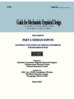
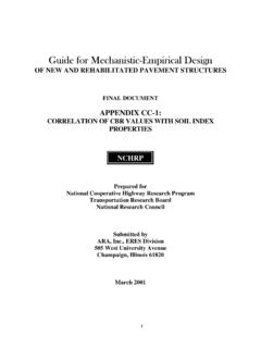
9 Through the use of this approach, an estimation of strength of a structural element can be made and the element appropriately detailed. Unlike the sectional methods of design, the strut-and tie method does not lend itself to a cook book approach and therefore requires the application of engineering judgment. ELEMENTS OF A Strut-and-Tie Model . As stated above, a Strut-and-Tie Model is comprised of three primary elements: struts, ties, and nodes. An illustration of the different components using a deep beam example is shown in Figure 1-1. Node StStrut Tie Strut Figure 1-1: Illustration of the different components of a Strut-and-Tie Model using a deep beam. 1. STRUTS. Most research and design specifications specify the limiting compressive stress of a strut as the product of the concrete compressive strength, f'c, and a reduction factor.
10 The reduction factor is often a function of the geometric shape (or type) of the strut. The shape of a strut is highly dependent upon the force path from which the strut arises and the reinforcement details of any reinforcement connected to the tie. As discussed by Schlaich and Sch fer, there are three major geometric shape classes for struts: prismatic, bottle-shaped, and compression fan (1991). Fig. 1- 2 shows an illustration of the three major geometric shape classes for struts applied to common deep beam STMs. Prismatic struts are the most basic type of strut. Prismatic struts have uniform cross-sections. Typically, prismatic struts are used to Model the compressive stress block of a beam element as shown in Fig.