Transcription of Verilog Tutorial - UMD
1 Verilog TutorialByDeepak Kumar don't makes any claims, promises or guarantees about the accuracy,completeness, or adequacy of the contents of this Tutorial andexpressly disclaims liability for errors and omissions in the contents ofthis Tutorial . No warranty of any kind, implied, expressed or statutory,including but not limited to the warranties of non infringement of thirdparty rights, title, merchantability, fitness for a particular purpose andfreedom from computer virus, is given with respect to the contents ofthis Tutorial or its hyperlinks to other Internet resources. Reference inthis Tutorial to any specific commercial products, processes, orservices, or the use of any trade, firm or corporation name is for theinformation, and does not constitute endorsement, recommendation, orfavoring by me. All the source code and Tutorials are to be used onyour own risk. All the ideas and views in this Tutorial are my own andare not by any means related to my is a HARDWARE DESCRIPTION LANGUAGE (HDL).
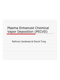
2 A hardware description Languageis a language used to describe a digital system, for example, a network switch, a microprocessoror a memory or a simple flip flop. This just means that, by using a HDL one can describe anyhardware (digital ) at any D flip flop Code2module d_ff ( d, clk, q, q_bar);3input d ,clk;4output q, q_bar;5wire d ,clk;6reg q, q_bar;78always@ (posedge clk)9begin10q <= d;11q_bar <= !d;12end1314endmoduleOne can describe a simple Flip flop as that in above figure as well as one can describe acomplicated designs having 1 million gates. Verilog is one of the HDL languages available in theindustry for designing the Hardware. Verilog allows us to design a Digital design at Behavior Level,Register Transfer Level (RTL), Gate level and at switch level. Verilog allows hardware designers toexpress their designs with behavioral constructs, deterring the details of implementation to a laterstage of design in the final engineers who want to learn Verilog , most often ask this question, how much time it will taketo learn Verilog ?
3 , Well my answer to them is "It may not take more then one week, if youhappen to know at least one programming language".Design StylesVerilog like any other hardware description language, permits the designers to design a design ineither Bottom up or Top down Up DesignThe traditional method of electronic design is bottom up. Each design is performed at thegate level using the standard gates ( Refer to the Digital Section for more details) With of new designs this approach is nearly impossible to maintain. New systems consist ofASIC or microprocessors with a complexity of thousands of transistors. These traditionalbottom up designs have to give way to new structural, hierarchical design methods. Without thesenew design practices it would be impossible to handle the new Down DesignThe desired design style of all designers is the top down design. A real top down design allowsearly testing, easy change of different technologies, a structured system design and offers manyother advantages.
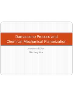
4 But it is very difficult to follow a pure top down design. Due to this fact mostdesigns are mix of both the methods, implementing some key elements of both design shows a Top Down design Levels of VerilogVerilog supports a design at many different levels of abstraction. Three of them are very important:Behavioral level Transfer Level Gate Level Behavioral levelThis level describes a system by concurrent algorithms (Behavioral). Each algorithm itself issequential, that means it consists of a set of instructions that are executed one after the , Tasks and Always blocks are the main elements. There is no regard to the structuralrealization of the Transfer LevelDesigns using the Register Transfer Level specify the characteristics of a circuit by operationsand the transfer of data between the registers. An explicit clock is used. RTL design contains exacttiming possibility, operations are scheduled to occur at certain times.
5 Modern definition of a RTLcode is "Any code that is synthesizable is called RTL code".Gate LevelWithin the logic level the characteristics of a system are described by logical links and their timingproperties. All signals are discrete signals. They can only have definite logical values (`0', `1', `X',`Z`). The usable operations are predefined logic primitives (AND, OR, NOT etc gates). Using gatelevel modeling might not be a good idea for any level of logic design. Gate level code is generatedby tools like synthesis tools and this netlist is used for gate level simulation and for OF VERILOGCHAPTER OF VERILOG8 History Of VerilogVerilog was started initially as a proprietary hardware modeling language by Gateway DesignAutomation Inc. around 1984. It is rumored that the original language was designed by takingfeatures from the most popular HDL language of the time, called HiLo as well as from traditionalcomputer language such as C.
6 At that time, Verilog was not standardized and the languagemodified itself in almost all the revisions that came out within 1984 to simulator was first used beginning in 1985 and was extended substantially implementation was the Verilog simulator sold by Gateway. The first major extensionwas Verilog XL, which added a few features and implemented the infamous "XL algorithm" whichwas a very efficient method for doing gate level time was late 1990. Cadence Design System, whose primary product at that time includedThin film process simulator, decided to acquire Gateway Automation System. Along with otherGateway product, Cadence now became the owner of the Verilog language, and continued tomarket Verilog as both a language and a simulator. At the same time, Synopsys was marketing thetop down design methodology, using Verilog . This was a powerful 1990, Cadence recognized that if Verilog remained a closed language, the pressures ofstandardization would eventually cause the industry to shift to VHDL.
7 Consequently, Cadenceorganized Open Verilog International (OVI), and in 1991 gave it the documentation for the VerilogHardware Description Language. This was the event which "opened" the did a considerable amount of work to improve the Language Reference Manual (LRM),clarifying things and making the language specification as vendor independent as it was realized, that if there were too many companies in the market for Verilog , potentiallyeverybody would like to do what Gateway did so far changing the language for their own would defeat the main purpose of releasing the language to public domain. As a result in1994, the IEEE 1364 working group was formed to turn the OVI LRM into an IEEE standard. Thiseffort was concluded with a successful ballot in 1995, and Verilog became an IEEE standard inDecember, Cadence gave OVI the LRM, several companies began working on Verilog simulators .
8 In1992, the first of these were announced, and by 1993 there were several Verilog simulatorsavailable from companies other than Cadence. The most successful of these was VCS, the VerilogCompiled Simulator, from Chronologic Simulation. This was a true compiler as opposed to aninterpreter, which is what Verilog XL was. As a result, compile time was substantial, but simulationexecution speed was much the meantime, the popularity of Verilog and PLI was rising exponentially. Verilog as a HDL foundmore admirers than well formed and federally funded VHDL. It was only a matter of time beforepeople in OVI realized the need of a more universally accepted standard. Accordingly, the board ofdirectors of OVI requested IEEE to form a working committee for establishing Verilog as an IEEE standard. The working committee 1364 was formed in mid 1993 and on October 14, 1993, it OF VERILOG9its first standard, which combined both the Verilog language syntax and the PLI in a single volume,was passed in May 1995 and now known as IEEE Std.
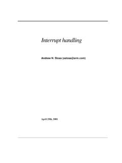
9 1364 many years, new features have been added to Verilog , and new version is called Verilog2001. This version seems to have fixed lot of problems that Verilog 1995 had. This version iscalled 1364 2000. Only waiting now is that all the tool vendors implementing OF VERILOG10 NOTES OF VERILOG11 DESIGN AND TOOL FLOWCHAPTER AND TOOL FLOW12 IntroductionBeing new to Verilog you might want to try some examples and try designing something new. Ihave listed the tool flow that could be used to achieve this. I have personally tried this flow andfound this to be working just fine for me. Here I have taken only front end design part of the toolflow and bit of FPGA design flow that can be done without any fat money spent on tools. If youhave any suggestions or questions please don't hesitate to mail me. ( Note : I have missed stepsin P&R, Will add then shortly)Various stages of ASIC/FPGAS pecification : Word processor like Word, Kwriter, AbiWord, Open Office.
10 High Level Design : Word processor like Word, Kwriter, AbiWord, for drawing waveformuse tools like waveformer or testbencher or Word, Open Office. Micro Design/Low level design: Word processor like Word, Kwriter, AbiWord, for drawingwaveform use tools like waveformer or testbencher or Word. For FSM StateCAD or somesimilar tool, Open Office. RTL Coding : Vim, Emacs, conTEXT, HDL TurboWriter Simulation : Modelsim, VCS, Verilog XL, Veriwell, Finsim, iVerilog, VeriDOS. Synthesis : Design Compiler, FPGA Compiler, Synplify, Leonardo Spectrum. You candownload this from FPGA vendors like Altera and Xilinx for free. Place & Route : For FPGA use FPGA' vendors P&R tool. ASIC tools require expensiveP&R tools like Apollo. Students can use LASI, Magic. Post Si Validation : For ASIC and FPGA, the chip needs to be tested in real design, device drivers needs to be in place. Figure : Typical Design AND TOOL FLOW13 SpecificationThis is the stage at which we define what are the important parameters of the system/design thatyou are planning to design.