Transcription of 10 Gigabit Ethernet Subsystem v3 - Xilinx
1 10 gigabit ethernet subsystem Product Guide Vivado Design Suite PG157 February 4, 2021. Table of Contents Chapter 1: Overview Feature Summary.. 8. Applications .. 9. Unsupported Features.. 10. Licensing and Ordering .. 10. Chapter 2: Product Specification Standards .. 13. Performance.. 13. Resource Utilization.. 13. Latency .. 13. Port Descriptions .. 15. Register Space .. 50. Chapter 3: Designing with the Subsystem Clocking.. 89. Resets .. 89. 7 Series Clocking and Shared Logic .. 90. UltraScale Device Clocking and Shared Logic Using the RX Elastic Buffer .. 92. UltraScale Device Clocking and Shared Logic Omitting the RX Elastic Buffer .. 97. Shared Logic for 7 Series IEEE 1588 Support .. 99. Ethernet Protocol Description.. 101. Connecting the Data Interfaces.. 107. IEEE 1588 Timestamping.
2 130. Connecting the Management Interface .. 139. IEEE Flow Control .. 144. Priority Flow Control .. 151. Receiver Termination.. 160. Special Design Considerations .. 160. Chapter 4: Design Flow Steps Customizing and Generating the Subsystem .. 167. Constraining the Subsystem .. 175. Simulation .. 177. 10Gb Ethernet Send Feedback 2. PG157 February 4, 2021 Synthesis and Implementation .. 177. Chapter 5: Example Design Shared Logic and the Support Layer .. 184. Chapter 6: Test Bench Appendix A: Upgrading Migrating to the Vivado Design Suite.. 189. Upgrading in the Vivado Design Suite .. 189. Appendix B: Debugging Finding Help on .. 193. Debug Tools .. 194. Hardware Debug .. 195. Appendix C: Additional Resources and Legal Notices Xilinx Resources .. 202. Documentation Navigator and Design Hubs.
3 202. References .. 202. Revision History .. 203. Please Read: Important Legal Notices .. 204. 10Gb Ethernet Send Feedback 3. PG157 February 4, 2021 . IP Facts Introduction Facts Table Subsystem Specifics The 10 Gigabit Ethernet subsytem provides a Supported 10 GBASE-R: UltraScale . 10 Gigabit Ethernet MAC and PCS/PMA in Device Zynq -7000. 10 GBASE-R/KR modes to provide a 10 Gigabit Family(1) (2) Virtex -7, Kintex -7(3). Ethernet port. The transmit and receive data 10 GBASE-KR: UltraScale , Virtex-7(4). interfaces use AXI4-Stream interfaces. An Supported User optional AXI4-Lite interface is used for the Interfaces AXI4-Lite, AXI4-Stream control interface to internal registers. Resources Performance and Resource Utilization web page Provided with Subsystem Features Design Files Encrypted RTL.
4 Designed to 10 Gigabit Ethernet specification Example Design verilog IEEE Standard Test Bench verilog AXI4-Stream protocol support on client TX Constraints File Xilinx Design Constraint (XDC). and RX interfaces. 64-bit AXI4-Stream is Simulation verilog or VHDL source HDL Model Model available for all permutations. For Supported 10 GBASE-R in supported devices, 32-bit S/W Driver Linux AXI4-Stream is available to provide lower Tested Design Flows(5). latency and utilization. Design Entry Vivado Design Suite Configured and monitored through an For supported simulators , see the optional AXI4-Lite Management Data Simulation Xilinx Design Tools: Release Notes Guide. interface or using status and configuration Synthesis Vivado Synthesis vectors Support Supports 10 GBASE-SR, -LR and -ER optical Release Notes links in Zynq-7000, UltraScale , Virtex-7, and Known Master Answer Record: 57358.
5 And Kintex-7 devices (LAN mode only) Issues Supports 10 GBASE-KR backplane links All Vivado IP. Master Vivado IP Change Logs:72775. Change Logs including Auto-Negotiation (AN), Training Xilinx Support web page and Forward Error Correction (FEC). Supports Deficit Idle Count Notes: 1. For a complete list of supported devices, see the Vivado IP. Comprehensive statistics gathering catalog. For new designs in the UltraScale/. UltraScale+ portfolio, see the 10G/25G Ethernet Subsystem Supports and flow control webpage. 2. For the listed 7 series families, only a -2 speed grade or faster Supports VLAN and jumbo frames is supported. Custom Preamble mode 3. -2, -2L or -3. 4. GTHE2 transceivers only. Independent TX and RX Maximum 5. For the supported versions of the tools, see the Transmission Unit (MTU) frame length Xilinx Design Tools: Release Notes Guid e.
6 Supports high accuracy IEEE Standard 1588-2008 1-step and 2-step timestamping on a 10 GBASE-R network interface 10Gb Ethernet Send Feedback 4. PG157 February 4, 2021 Product Specification Chapter 1. Overview The 10G Ethernet Subsystem provides 10 Gb/s Ethernet MAC, Physical Coding Sublayer (PCS) and Physical Medium Attachment (PMA) transmit and receive functionality over an AXI4-Stream interface. The Subsystem is designed to interface with a 10 GBASE-R. Physical-Side Interface (PHY) or a 10 GBASE-KR backplane and is designed to the IEEE. Standard , Carrier Sense Multiple Access with Collision Detection (CSMA/CD). Access Method and Physical Layer Specifications (IEEE Std ) [Ref 1]. The 10 GBASE-KR Subsystem is distinguished from the 10 GBASE-R Subsystem by the addition of a Link Training block as well as optional Auto-Negotiation (AN) and Forward Error Correction (FEC) features, to support a 10 Gb/s data stream across a backplane.
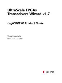
7 The Subsystem also provides an optional high accuracy timestamping capability compatible with IEEE Std 1588-2008 (also known as IEEE1588v2). This is available for the 10 GBASE-R. standard. Figure 1-1 shows the block diagram of the 10G Ethernet MAC Subsystem . X-Ref Target - Figure 1-1. Optional AXI4-Lite Management Interface 0',2 0',2. 10 Gigabit Ethernet Serial AXI4-Stream 10 Gigabit Ethernet PCS/PMA. MAC Internal (10 GBASE-R or XGMII 10 GBASE-KR). Timer Sync Timer Sync (optional for 1588) (optional for 1588). System Timer X13598. Figure 1-1: 10G Ethernet MAC Block Diagram 10Gb Ethernet Send Feedback 5. PG157 February 4, 2021 Chapter 1: Overview 10G Ethernet MAC. X-Ref Target - Figure 1-2. ;LOLQ[ )3*$. &RUH. VBD[LVBW[BWGDWD. VBD[LVBW[BWNHHS . VBD[LVBW[BWYDOLG. VBD[LVBW[BWODVW 7 UDQVPLW (QJLQH.]]]]]]]]]
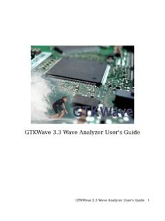
8 VBD[LVBW[BWUHDG\. VBD[LVBW[BWXVHU. *%$6( 5 RU *%$6( .5.. 5 HFRQFLOLDWLRQ 6 XEOD\HU. VBD[LVBSDXVHBWYDOLG. VBD[LVBSDXVHBWGDWD. $;, 6 WUHDPLQJ.. 8 VHU/RJLF. )ORZ &RQWURO. PBD[LVBU[BSIFBS>[@BWYDOLG . PBD[LVBU[BWGDWD . PBD[LVBU[BWNHHS . PBD[LVBU[BWYDOLG . 5 HFHLYH (QJLQH. PBD[LVBU[BWODVW. PBD[LVBU[BWXVHU. 0 DQDJHPHQW %ORFN. &RQILJ 6 WDWLVWLFV. $;, /LWH. 8 VHU/RJLF. :UDSSHU. $;, /LWH. ,QWHUUXSW &RQWURO 0',2. Figure 1-2: 10G Ethernet MAC Block Diagram Figure 1-2 illustrates the 10G Ethernet MAC block diagram. The major functional blocks include the following: Transmit Engine which formats the frame and interframe gap Receive Engine which decodes frames and performs error checking on them Flow Control, either legacy mode or priority flow control Reconciliation Sublayer which interfaces the MAC to the connected 10 GBASE-R/10 GBASE-KR core Optional Management Block which provides an AXI4-Lite interface for configuration, access to internal statistical counters, and to the MDIO registers of the connected 10 GBASE-R/10 GBASE-KR core 10Gb Ethernet Send Feedback 6.))]]]]]]]]]]]]]]]]]]]
9 PG157 February 4, 2021 Chapter 1: Overview 10 GBASE-R. For Zynq -7000, UltraScale , Virtex -7, and Kintex -7 devices, all of the PCS and management blocks illustrated are implemented in logic, except for part of the Gearbox and SERDES. Figure 1-3 shows the architecture. X-Ref Target - Figure 1-3. Fabric GT. Elastic 64b66b Block rxn,p Descramble Buffer Decode Sync Test 10- Pattern Gigabit Check BER Mon Ethernet PCS SERDES. MAC. Test Pattern Generate Phase 64b66b Scramble Gearbox Encode FIFO txn,p XGMII (SDR). MDIO Control PCS/PMA. +. Registers Status X12649. Figure 1-3: 10 GBASE-R Block Diagram The major functional blocks include the following: Transmit path, including scrambler, 64b/66b encoder and Gearbox Receive path, including block synchronization, descrambler, decoder and BER (Bit Error Rate) monitor Elastic buffer in the receive datapath.
10 The elastic buffer is 32 words deep (1 word = 64bits data + 8 control). If the buffer empties, local fault codes are inserted instead of data. This allows you to collect up to 64. clock correction (CC) sequences before the buffer overflows (and words are dropped). The buffer normally fills up to one half and then deletes CC sequences when over half full, and inserts CC sequences when under one half full. So from a half-full state, you can (conservatively) accept an extra 360 KB of data (that is, receiving at +200 ppm) without dropping any. From a half-full state you can cope with another 360 KB of data without inserting local faults (for 200 ppm). Test pattern generation and checking Serial interface to optics Management registers (PCS/PMA) with optional MDIO interface 10Gb Ethernet Send Feedback 7.