Transcription of VERTEX - MT Ortho
1 VERTEX Reconstruction System Surgical Techniqueas described by:Kevin Foley, MDSemmes Murphey Clinic Memphis, TennesseeSteve Papadopoulos, MDBarrow Neurological Institute Phoenix, ArizonaRick Sasso, MDIndiana Spine Group Indianapolis, Indiana Surgical TechniqueVERTEX Reconstruction SystemMEDTRONICDear Colleague:We believe that there is a need to better address the surgical challenges we face in the posterior cervical and upper thoracic spine. Current instrumentation systems limit the ability to effectively meet all clinical and anatomical requirements. Although we ve seen a recent evolution of posterior cervical and upper thoracic systems, they lack the modularity and versatility needed to address the most challenging considerable thought, we determined that our design goal was a system with a variety of modular components that offer different options for spinal fixation that attach to a longitudinal rod.
2 The VERTEX Reconstruction System is comprised of cervical laminar hooks, thoracic multi axial screws, and lateral offset laminar hooks are designed to provide excellent fit and fixation to the sub-axial cervical and upper thoracic spine. The multi axial thoracic screw offers a degree of angulation and independent screw placement that reduces the need to contour the rod. The articulating saddle of the multi axial screw allows for easy rod attachment. A lateral offset connector provides a way to connect non-linear multi axial screws to the rod. This enables us to best fit the anatomy of our , the VERTEX Reconstruction System allows us the ability to effectively treat degenerative disc disease, spondylolisthesis, spinal stenosis, fractures, failed previous fusions, and tumors with more intra-operative options than ever before.
3 The ability to treat a patient s condition without compromising stabilization due to the constraints of the instrumentation is a new VERTEX Reconstruction System is a versatile system that is easy to use, and is designed to be effective in treating the more challenging cases in the posterior cervical and upper thoracic spine. The following monograph introduces the VERTEX Reconstruction System, as well as personal thoughts reflecting our current clinical practice and operative , Kevin Foley, MD Steve Papadopoulos, MD Rick Sasso, MDIntroduction Surgical TechniqueVERTEX Reconstruction SystemMEDTRONICI mplants.
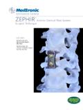
4 3 Instrument Set ..4 5 Patient Positioning/Posterior Approach ..6 Surgical Technique Steps ..7 6 Preoperative Planning ..7 Drilling ..8 Determining Screw Length ..9 Tapping and Screw Insertion .. 0 Rod Placement .. 3 Using Lateral Connectors.. 4 Set Screw Placement .. 5 Tightening Set Screws .. 6 Hook Placement .. 7 9 CROSSLINK Connector Placement .. 0 Rod Connector Placement .. Product Ordering Information .. Important Product Information .. 3 5 Table of Contents3 Surgical TechniqueVERTEX Reconstruction SystemMEDTRONICL aminar HookAttaches directly to rodExcellent sizes for cervical lamina Titanium Rod Easily contours to meet individual patient anatomy Set Screw Buttress threads reduce profile and improves cross-threading resistance Internal set screw allows for placement and visualization Lateral Connector Accommodates rod attachment of non-linear screws Allows for increased angle of screw trajectoryAccounts for screw height differences CROSSLINK ConnectorIncreases construct rigidity Crossbar can be contoured to avoid
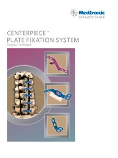
5 Posterior elements Diameters Multi Axial Thoracic Screw Allows for 60 degree conical screw angulation, or 30 degrees in any directionTop loading allows for independent placementRotating saddle reduces rod contouring Rod Connector Connects 3. mm rod to or rod Implants4 Surgical TechniqueVERTEX Reconstruction SystemMEDTRONICD rill Adjustable Cortical Adjustable Cancellous TapScrewdriverAwlPedicle ProbeStraight Hex ScrewdriverDrill Bit HandleDrill Bit, Cancellous AdjustableDrill Bit, Cancellous 4mmDrill Bit, Cortical Adjustable Cancellous TapDepth GaugeAlignment ToolCircular Drill Bit AdapterDrill Stop.
6 AdjustableInstrument Set5 Surgical TechniqueVERTEX Reconstruction SystemMEDTRONICI nstrument SetRod HolderRod Pusher/Counter Torque Rod CutterCompressorDistractor Bending Iron LeftBending Iron RightHook HolderLaminar ElevatorRod BenderRod Reducer6 Surgical TechniqueVERTEX Reconstruction SystemMEDTRONICThe following surgical technique describes the application of the VERTEX Reconstruction System utilizing upper thoracic pedicle screw fixation for illustrative purposes. Refer to the package insert for a complete list of indications and patient is placed prone in an appropriate manner to avoid specific pressure points.
7 The head may be placed in a padded head holder or secured in three point pins. The back and neck are prepped and draped in a sterile fashion (Figure 1). A midline incision is made and dissection is carried down to the spinous processes of the appropriate paraspinous musculature is elevated in a sub-periosteal plane. Dissection is carried laterally to expose the facets and the transverse processes. Attention is given to the preservation of the most cephalad facet capsule while all other soft tissue is removed from the facets to be included in the fusion. Attention is now directed toward instrumentation of the 1 Patient Positioning/Posterior Approach7 Surgical TechniqueVERTEX Reconstruction SystemMEDTRONICThe following technique describes the placement of VERTEX Screws within the pedicle at T T3.
8 Anatomical landmarks are identified and carefully reviewed to determine the entry point to the pedicle. Anatomical variations should be noted on inspection of preoperative CT scans and AP radiographs. The surgeon may chose to utilize an image guided surgical navigation system such as the STEALTHSTATION Treatment Guidance Platform* or the FLUORONAV Virtual Fluoroscopy System*. Additionally, intraoperative imaging may be utilized to facilitate thoracic pedicle screw placement. If a laminectomy or laminotomy is performed the pedicle may be directly visualized and/or palpated. An entry hole is made over the pedicle with a burr, drill, or sharp trocar (Figure 2).
9 Figure 2 The anatomical landmarks for entry into the pedicle of the upper thoracic spine are the intersection of a line parallel to the upper 1/3 of the transverse process and a vertical line through the middle aspect of the upper facet joint. This ends up approximately 3 to 4mm caudal to the mid aspect of the upper facet joint. Dr. Rick Sasso I routinely use StealthStation guidance for placement of upper thoracic pedicle screws. Dr. Kevin FoleyPreoperative Planning* Please see your sales represenatative for technical information and/or the package insert for STEALTHSTATION Treatment and Guid-ance platform FLUORONAV Virtual TechniqueVERTEX Reconstruction SystemMEDTRONICD rillingThe drill guide is used to align either the 4mm fixed cancellous drill bit (Figure 3), an adjustable depth cancellous drill bit or an adjustable depth cortical drill bit (Figure 4).
10 A pilot hole is then drilled to the desired depth and trajectory. The drill bit may be attached to the drill bit handle for manual drilling or attached to a power drill with or without the use of the circular drill bit adapter. Figure 3 Instead of a drill, I use a forage technique with a small straight curette. Dr. Rick Sasso I routinely drill to a depth just beyond the base of the thoracic pedicle and tap into the vertebral body. Dr. Steve PapadopoulosFigure 49 Surgical TechniqueVERTEX Reconstruction SystemMEDTRONICD etermining Screw LengthThe depth gauge is then used to gently palpate the cancellous bone of the pedicle and to determine screw length (Figure 5).