Transcription of Vertical-Cavity Surface-Emitting Laser Technology
1 Princeton Optronics, Inc. * 1 Electronics Drive * Mercerville, New Jersey 08619 Voice: (609) 584-9696 * Fax: (609) 584-2448 * E-mail: * Vertical-Cavity Surface-Emitting Laser Technology Introduction Vertical-Cavity Surface-Emitting Lasers (VCSELs) are a relatively recent type of semiconductor lasers. VCSELs were first invented in the mid-1980 s. Very soon, VCSELs gained a reputation as a superior Technology for short reach applications such as fiber channel, Ethernet and intra-systems links. Then, within the first two years of commercial availability (1996), VCSELs became the Technology of choice for short range datacom and local area networks, effectively displacing edge-emitter lasers.
2 This success was mainly due to the VCSEL s lower manufacturing costs and higher reliability compared to edge-emitters. Princeton Optronics has developed the key technologies resulting in the world's highest power single VCSEL devices and 2-D arrays. We have successfully demonstrated single devices with >5W CW output power and large 2D arrays with >230W CW output power. We have made single mode devices of 1W output power and single mode arrays with power of >100W which are coupled to 100u, fiber. The highest wall plug efficiency of these devices and arrays is 56%.
3 We have made arrays which deliver 1kW/cm2 in CW operation and in QCW operation. Princeton Optronics was a participant in the DARPA-SHEDS program, whose main objective was to improve Laser diode conversion efficiency. The VCSEL structure Semiconductor lasers consist of layers of semiconductor material grown on top of each other on a substrate (the epi ). For VCSELs and edge-emitters, this growth is typically done in a molecular-beam-epitaxy (MBE) or metal-organic-chemical-vapor-deposition (MOCVD) growth reactor. The grown wafer is then processed accordingly to produce individual devices.
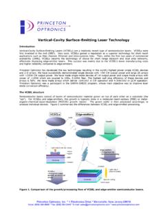
4 Figure 1 summarizes the differences between VCSEL and edge-emitter processing. Figure 1. Comparison of the growth/processing flow of VCSEL and edge-emitter semiconductor lasers. Princeton Optronics, Inc. * 1 Electronics Drive * Mercerville, New Jersey 08619 Voice: (609) 584-9696 * Fax: (609) 584-2448 * E-mail: * In a VCSEL, the active layer is sandwiched between two highly reflective mirrors (dubbed distributed Bragg reflectors, or DBRs) made up of several quarter-wavelength-thick layers of semiconductors of alternating high and low refractive index.
5 The reflectivity of these mirrors is typically in the range ~ As a result, the light oscillates perpendicular to the layers and escapes through the top (or bottom) of the device. Current and/or optical confinement is typically achieved through either selective-oxidation of an Aluminum-rich layer, ion-implantation, or even both for certain applications. The VCSELs can be designed for top-emission (at the epi/air interface) or bottom-emission (through the transparent substrate) in cases where junction-down soldering is required for more efficient heat-sinking for example.
6 Figure 2 illustrates different common types of VCSEL structures. In contrast, edge-emitters are made up of cleaved bars diced from the wafers. Because of the high index of refraction contrast between air and the semiconductor material, the two cleaved facets act as mirrors. Hence, in the case of an edge-emitter, the light oscillates parallel to the layers and escapes side-ways. This simple structural difference between the VCSEL and the edge-emitter has important implications. Since VCSELs are grown, processed and tested while still in the wafer form, there is significant economy of scale resulting from the ability to conduct parallel device processing, whereby equipment utilization and yields are maximized and set up times and labor content are minimized.
7 In the case of a VCSEL (see Figure 1), the mirrors and active region are sequentially stacked along the Y axis during epitaxial growth. The VCSEL wafer then goes through etching and metalization steps to form the electrical contacts. At this point the wafer goes to test where individual Laser devices are characterized on a pass-fail basis. Finally, the wafer is diced and the lasers are binned for either higher-level assembly (typically >95%) or scrap (typically <5%). The following Figure shows a single high-power VCSEL device (>2W output power) packaged on a high-thermal conductivity submount.
8 SubstrateHeat-spreaderLight outputN-contactDBRsActive regionP-contactSubstrateSubstrateProton implantationOxide apertureOxide aperture(a)(b)(c)SubstrateHeat-spreaderL ight outputN-contactDBRsActive regionP-contactSubstrateSubstrateProton implantationOxide apertureOxide aperture(a)(b)(c)Figure 2. Three common types of VCSEL structures: (a) a top-emitting structure with proton implantation to confine the current, (b) a selectively-oxidized top-emitting structure to confine the optical modes and/or the current, and (c) a mounted bottom-emitting selectively-oxidized structure.
9 Figure 3. Packaged high-power VCSEL device (>2W). The submount is 2mm x 2mm. Princeton Optronics, Inc. * 1 Electronics Drive * Mercerville, New Jersey 08619 Voice: (609) 584-9696 * Fax: (609) 584-2448 * E-mail: * In a simple Fabry-P rot edge-emitter the growth process also occurs along the Y axis, but only to create the active region as mirror coatings are later applied along the Z axis. After epitaxial growth, the wafer goes through the metallization step and is subsequently cleaved along the X axis, forming a series of wafer strips. The wafer strips are then stacked and mounted into a coating fixture.
10 The Z axis edges of the wafer strips are then coated to form the device mirrors. This coating is a critical processing step for edge-emitters, as any coating imperfection will result in early and catastrophic failure of the devices due to catastrophic-optical-damage (COD). After this coating step, the wafer strips are diced to form discrete Laser chips, which are then mounted onto carriers. Finally, the Laser devices go into test. It is also important to understand that VCSELs consume less material: in the case of a 3 wafer, a Laser manufacturer can build about 15,000 VCSEL devices or approximately 4,000 edge-emitters of similar power levels.