Transcription of VERTICAL INLINE CENTRIFUGAL PUMPS - Grundfos
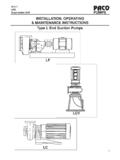
1 10/03 PPPPPACOACOACOACOACO PUMPSINSTALLATION, OPERATION& MAINTENANCE INSTRUCTIONSVERTICAL INLINE CENTRIFUGAL PUMPST ypes VL, VLS, 10/03 PPPPPACOACOACOACOACO PUMPSTABLE OF MECHANICALPAGEA. Pump 3B. 3C. Temporary 3D. 3E. Mounting of 4F. Securing The Base Plate (Type VLF Only).. 4G Piping General .. 4H. Suction (Inlet) (Outlet) 5J. Shaft Sealing General Packed PUMPS (Optional, Type VLF Only) .. 6L. Mechanical 6II. INSTALLATION- ELECTRICALA. Motors, 6B. Installation 7B. Pre-Start 7C. Motor Rotation .. 7D. Starting The 7E. Voltage 8F. Pump 8G. Short Duration 8H. Extended Period 8IV. MAINTENANCEA. Motor 8B. Pump Lubrication (Type VLF Only)..9V. DISASSEMBLY & ASSEMBLYA. Preparations for 10B.
2 Seal Bearing 11D. Sleeve 11E. Wear Ring 12F. 12VI. ORDERING 20X. SALES AND SERVICE 20 This safety symbol is used to alert Equipment Users of potential hazards. CAUTIONS are used toindicate potential hazardous situations which, if not avoided, may result in personal injury or damage toequipment. WARNINGS are used to indicate potential hazardous situations which, if not avoided, couldresult in serious personal injury or death. Always obey safety messages that follow this 10/03 PPPPPACOACOACOACOACO PUMPSRead these instructions thoroughly before installingand operating your PACO VERTICAL INLINE CentrifugalPump. Successful operation depends on carefulattention to the procedures described in Sections I, II, IIIand IV of this manual. Keep this instruction manualhandy for future PUMP IDENTIFICATION All PACO PUMPS are identified by Catalog and SerialNumbers.
3 These numbers are stamped on thepump nameplate ( a) affixed to each pumpvolute casing, and should be referred to in allcorrespondence with the first digits in the Catalog Number (preceding the firsthyphen) are known as the Product Code. The ProductCode may be 2 or 3 digits in length. This installation,Operation and Maintenance Manual applies to thefollowing Product Codes. NOTE: Hyphens may notappear on the Type VL, INLINE CENTRIFUGAL Pump,Close Coupled17 PACO Type VLS, INLINE CentrifugalPump, Split-coupled (rigid coupled)127 PACO Type VLF, INLINE CentrifugalPump, Flex-coupledB. RECEIVING Check pumping unit for shortage and damageimmediately upon arrival. Pump accessories whenrequired are packaged in a separate container andshipped with the 1a If equipment is damaged in transit, promptly reportthis to the carrier s agent.
4 Make complete notationson the freight bill to speed satisfactory adjustmentby the carrier. Unload and handle the unit with a : Do not lift pump assembly bymotor eye bolts alone. Motor eye bolts are notdesigned to support weight of entire TEMPORARY STORAGE If pump is not to be installed and operated soon afterarrival, store it in a clean, dry area of moderateambient temperature. Rotate the shaft by hand monthly to coat bearingwith lubricant to retard oxidation and corrosion. Follow motor manufacturer s storage recommenda-tions where LOCATION Locate the pump as close to the suction supply aspossible. Use the shortest and most direct suctionpiping practical. Refer to paragraph H. SUCTION(INLET) PIPING. Locate the pump below system level whereverpossible. This will facilitate priming, assure asteady liquid flow, and provide a positive suctionhead.
5 Make sure sufficient NPSH (Net Positive SuctionHead) is provided at the suction end by consideringthe pump s location in relation to the entire NPSH must always equal or exceedrequired NPSH specified on the pump performancecurve. Always allow sufficient accessibility for maintenanceand inspection. Provide a clear space with amplehead room for use of a hoist strong enough to lift thepump/motor assembly. Make sure a suitable power source is available forthe pump motor. Electrical characteristics shouldmatch those specified on the motor data plate,within the limits covered in Sections II and III. Avoid pump exposure to sub-zero temperatures toprevent pump liquid from freezing. If freezing condi-tions exist during shutdown periods, see SectionsIII-G and III-H for specific #:16-40957-130101-1782 STOCK #:SER #: #####2690301 BROOKSHIRE, TEXAS34014412 PUMPS : :65 SECTION I.
6 INSTALLATION- 10/03 PPPPPACOACOACOACOACO PUMPSE. MOUNTING OF PUMPPACO INLINE CENTRIFUGAL PUMPS may be mounted on theequipment room floor, or suspended in the piping,depending on the size and configuration of the following instructions shall apply:FLOOR MOUNTED PUMPS (VL, VLS & VLF) PUMPS mounted on equipment room floors should bepermanently installed on a firm, concrete foundation,mounting pad or spring isolation base of sufficient size todampen any vibration and prevent any deflection (ormisalignment VLF). Suitable anchor bolts shall be usedto secure the pump assembly to the pad or PUMPS (Type VL & VLS Only)PACO INLINE CENTRIFUGAL PUMPS , when properly supported,may be suspended in system piping. Pipe supports mustbe used on piping immediately adjacent to the pump.
7 Pipesupports must be adequately sized to support the weightof pump and piping, full of liquid, and shall be designed toeliminate transmission of noise or vibration. PACO Inlinepumps are designed to be mounted in horizontal pipe runswith motor positioned vertically upward. Alternatively, PUMPS with motor frame sizes of 256JM/JP or smallermay be mounted in VERTICAL pipe runs (risers) or in horizontalpipe runs with motors mounted horizontally. Consult PACOF actory for suitability of mounting with larger motors. Inno case shall motors be mounted vertically downward(upside down, with motor positioned below the pump).F. SECURING THE BASE PLATE (Type VLF only) After the concrete pad has been poured and set,lower the pump base plate over the anchor bolts andrest it on loose adjustment wedges or shims placednear each anchor bolt and at intervals not to exceed24 along each or wedges must be placed to raise thebottom of the base 3/4 to 1-1/4 above the pad,allowing clearance for grout.
8 Level the pump shaft,flanges, and base plate using a spirit level, adjustingthe wedges or shims, as required. Check to make sure that the piping can be alignedto the pump flanges without placing any strain oneither flange. After pump alignment has been established, putnuts on foundation bolts and tighten them justenough to keep the unit base plate from a form or dam around the concrete padand pour grout in and around the pump base. Groutcompensates for uneven foundation, distributes theweight of the unit, and prevents shifting. Use anapproved, nonshrinking grout (such as Embeco 636by Master Builders, Cleveland, Ohio or equivalent).Allow at least 24 hours for this grout to set beforeproceeding with piping connections. After the grout has thoroughly hardened, check thefoundation bolts and tighten if necessary.
9 Recheckthe pump alignment after the foundation bolts PIPING-GENERAL Do not use pump as a support for piping! Usepipe hangers or other supports at proper intervals toprovide complete piping support near the pump. Both suction and discharge piping should beindependently supported and properly aligned sothat no strain is transmitted to the pump when flangebolts are tightened. Make sure piping is as straight as possible, avoidingunnecessary bends and fittings. Where necessary,use 45 or long-sweep 90 pipe fittings to decreasefriction loss. Where flanged joints are used, make sure thatinside diameters properly match and mounting holesare aligned. Do not spring or force piping when making anyconnections!H. SUCTION (INLET) PIPINGThe sizing and installation of suction piping is particu-larly important.
10 It must be selected and installed in amanner that minimizes pressure loss and permitssufficient liquid flow into the pump during starting andoperation. Many NPSH problems can be traced directlyto improper design of suction piping systems. Observethe following precautions when installing suction piping: Suction piping should be as direct as possible, andideally the length should be at least ten times thepipe diameter. Short suction piping can be the samediameter as the suction opening. Longer pipingshould be one or two sizes larger (depending onlength), reducing to the diameter of the pumpsuction 10/03 PPPPPACOACOACOACOACO PUMPS Use an eccentric reducer, with the eccentric sidedown (Fig. 2a) when reducing the pipe diameter tothe diameter of suction opening. At no point should suction piping be smaller indiameter than the pump suction opening.