Transcription of Vickers Accessories Pressure Switches
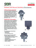
1 Pressure switchsymbolISO 4400connectorP112233 SupplyPin 1 Normally closedPin 2 Normally openPin 3 March 1996GB-2166AS*307 SeriesSectional ArrangementST307-V2-AS-H2 exampleGeneral DescriptionA range of piston-operated pressureswitches for general applications where anelectrical signal is needed to indicate agiven Pressure condition in a microswitch is actuated by theoperating plate of an adjustable loadingspring. The spring load holds the operatingplate against the switch until appliedhydraulic Pressure on a small piston forcesthe operating plate away from the switch tochange over the switch contacts. Theswitch will reset when the hydraulicpressure falls by a small in three Pressure adjustmentranges are available for panel or basemounting with G1/4I (BSPF) or SAE/UNFport connection, or for subplate options are screwdriver orhandknob (both with locking screw) orhandknob with keylock.
2 Pressure switchesare supplied complete with an ISO 4400(DIN 43650) type connector stacking adaptor blocks to ISO 4401 size 03 are available to allowpressure Switches to be installed intocompact stack assemblies using VickersSystemStakTM valves (see catalog 2027).Functional SymbolFeatures and BenefitsFSwitching accuracy less than 1% of Pressure settingFLow hysteresisFSuitable for AC or DC currentFGalvanic gold-plated silver switch contacts for long lifeFSmall, easy to installFElectrical protection to IEC 144 class IP65 FSelect requirements from:3 Pressure ranges 3 adjustment types3 mounting stylesLocking screw and keylock optionsVickers AccessoriesPressure SwitchesModel CodeSHydraulic system connectionT = Threaded pipe connectionG = O-seal for subplate connectionMountingBlank = Two tapped holes for base mounting (type T only)SCH = Panel mountingF= Subplate mountingType of adjustmentBlank =Screwdriver slot with locking set screwV2=Knurled handknob with locking set screwV2-AS-H2 = Knurled handknob with keylock307(-**)534123425*1- (**-**-**) ** (-*)For Stacking Adaptor BlocksDGMP-3 - * - * -1 *1234 Valve/subplate mountinginterface3 = ISO 4401 size 03(ANSI , size D03)Port connection to Pressure switchP = Port P (at A end of block)A = Port A (at A end of block)
3 B = Port B (at B end of block)- Pressure switch mounting bolttappingsB = MetricS = UNCD esign number, 10 seriesSubject to change. Installationdimensions unchanged for designnumbers 10 to 19 adjustment range55 =5 to 55 bar (73 to 797 psi)150 =20 to 150 bar (290 to 2175 psi)350 =20 to 350 bar (290 to 5075 psi)Thread combinations:port/mounting bolt tappingsB=G1/4I (BSPF) port and/or metric mountings ST307 models only:S = SAE 6 port and/or UNC mountings2 For Pressure Switches43 Operating DataPressure SwitchesMaximum Pressure , all models350 bar (5075 psi) Pressure adjustment rangesSee model code position Electrical dataCurrent capacitySwitching connectionsConnector plug (supplied)Protection (general)See Switching Capacity belowSee Functional Symbol page 1 Female receptacle to ISO 4400 (DIN 43650)IEC 144 class IP65 Microswitch detailsTypeTravelContactsProtectionElect romechanical, double-throw0,5 mm ( )Refined silver, galvanic gold-platedIEC 144 class IP67.
4 Dustproof to DIN 40050 Switching repeatability<1%Hydraulic fluidsAntiwear hydraulic oil or water-in-oil emulsionsFluid temperatures 50_C to +100_C ( 58_F to +212_F)Main housing materialsAluminium and brassMass0,62 kg ( lb)Stacking Adaptor BlocksMass1 kg ( lb)Switching CapacityAC currentVoltageResistiveload (A)Bulb load,metallic filament (A)Inductiveload (A)110 to 125220 to currentVoltageResistiveload (A)Bulb load,metallic filament (A)NCYNOYI nductiveload (A)Up to 15>15 to 30>30 to 50>50 to 75>75 to 125>125 to normally closed (NC) and normally open (NO) contacts returnpressure diiferential(on falling Pressure )Switch operating point(on rising presssure) settingbarpsi46010050 Return Pressure differentialEffective adjustment range25752851030505573200400600798020150 bar010002000psiPressure settingbarpsi41216020015010050S*307- - -350 modelsReturn Pressure differentialEffective adjustment range8250300040005075290 Average limits2010050200250300350020406080100120 140 150 bar0290 500100015002000 2175 psiPressure settingbarpsi41216020015010050S*307- - -150 modelsReturn Pressure differentialEffective adjustment range8S*307- - -55 modelsMax.
5 LimitMin. limitMax. limitMin. limitMax. limitMin. limit4 Hysteresis DiagramsThe Pressure differential betweenswitching point (on rising Pressure ) andswitch reset point (on falling Pressure )varies according to the switching point PointsExample 1 ( bar units of Pressure )Model S*307---150 set at 140 barMax. reset pressure134 bar.. Average reset pressure132 bar.. Min. reset pressure130 bar.. At this level the return Pressure differentialmay vary between 6 and 10 bar, the average being 8 2 ( psi units of Pressure )Model S*307---150 set at 2000 psiMax. reset pressure1910 psi.. Average reset pressure1880 psi.. Min. reset pressure1860 psi.. At this level the return Pressure differentialmay vary between approximately 90 and140 psi, the average being 120 Dimensions mm (inches)23rd angleprojection2 holes for mounting screws,tapped according to modelcode position :With knurled handknob adjuster and locking screwST307-V2-**-BST307-V2-**-SDimension s/data not shown are as for model above, as knurled handknob adjuster and keylockST307-V2-AS-H2-**-BST307-V2-AS-H2 -**-SDimensions/data not shown are as for model above, as screwdriver adjustment and locking screwST307-**-BST307-**-SHydraulic connection, tappedaccording to model codeposition :5B = G1/4 (1/4I BSPF)x 9 ( ) =9/16I-18 UNF-2Bx fitting torque.
6 30 Nm (265 lbf in)27 ( ) A/FPg11114 ( )60 ( )86 ( )44 ( )Locking screw2,5 ( ) A/FAdjustmentscrewB = M5 x 10 deepS = #10-24 UNC x deep40( )85 ( )40( )13 ( ) for plug removal32( )Locking screw2,5 ( ) A/FAdjustmentknobKey must be inserted and turned to allow not possible (knob spins freely) when key is Mounted Models, Blank at Model Code Position 23rd angleprojectionWith knurled handknob adjuster and locking screwST307-SCH-V2-**-BST307-SCH-V2-**-SD imensions/data not shown are as for model above, as knurled handknob adjuster and keylockST307-SCH-V2-AS-H2-**-BST307-SCH- V2-AS-H2-**-SDimensions/data not shown are as for model above, as ( )85 ( )114 ( )60 ( )15( )86 ( )40 ( )44 ( ) bolt circle dia. 35( dia)Locking screw2,5 ( ) A/FAdjustmentscrew2 holes for mounting screws,tapped according to modelcode position :B = M5 x 10 deepS = #10-24 UNC x deepHydraulic connection,tapped according to modelcode position :5B = G1/4 (1/4I BSPF)x 9 ( ) =9/16I-18 UNF-2Bx fitting torque.
7 30 Nm (265 lbf in)27 ( ) A/F13 ( ) for plug removalLocking screw2,5 ( ) A/FAdjustmentknobKey must be inserted and turned to allow not possible (knob spins freely) when key is for Panel Mounting, SCH at Model Code Position With screwdriver adjustment and locking screwST307-SCH-**-BST307-SCH-**-S3rd angleprojection2 With knurled handknob adjuster and locking screwSG307-F-V2-**-BSG307-F-V2-**-SDimen sions/data not shown are as for model above, as knurled handknob adjuster and keylockSG307-F-V2-AS-H2-**-BSG307-F-V2-A S-H2-**-SDimensions/data not shown are as for model above, as ( )13 ( ) for plugremoval40 ( )44 ( ) bolt circle screw2,5 ( ) A/FAdjustment screw4 holes through, 5,5 ( )FPg11100 ( )61 ( )60 ( )Mounting face:O-seal 7 ( ) i/dia x 1,5 ( dia) section,suppliedF Only two mounting bolts required, see Mounting Surface, this screw2,5 ( ) A/FAdjustmentknobKey must be inserted and turned toallow not possible (knob spinsfreely) when key is Surfacefor Model Types SG307-FValve can be positioned in 90_ stepsaround axis, and dependent on spacefor electrical ( )bolt circle surface,40 x 40 ( x ), cleanand free from connection topressure switch, 5 ( dia) holes tapped M5 or#10-24 UNC, orequivalent (user s option)85 ( )7 Subplate Mounted Models, F at Model Code Position With screwdriver adjustment and locking screwSG307-F-**-BSG307-F-**-SPT BADGMP-3-P-*-1*PPT BADGMP-3-A-*-1*APT BADGMP-3-B-*-1*BFunctional SymbolsAPBT44 ( )
8 Bolt circle holes tapped according to model type:DGMP-3-*-B-1*: M5 x 10 deepDGMP-3-*-S-1*:#10-24 UNC x deepAB76,0 ( )46,0( )40,0( )40,5( )C3,5 ( ) 3,0( dia)31,75( )31,0 ( )View on A (port A end of block) formodel types: DGMP-3-P-*-1*DGMP-3-A-*-1*View on B (port B end of block) formodel type:DGMP-3-B-*-1*View on C 5,5 ( dia)through for 4mounting boltsThrough ports 7,0 ( dia)4 off O-seals suppliedSwitch as installed on face A (model type SG307-F shown).In all cases, valves can bepositioned in 90_ steps aroundaxis, and dependent on space forelectrical Dimensions 4,0 ( dia) x 4,25 ( )deep for orientation pin8 Stacking Adaptor BlocksAllows type SG307 Switches to beincorporated into Vickers ProcedureSpecify full model code for pressureswitches and for stacking adaptor PartsNo spare parts are available for productsshown in this catalog.