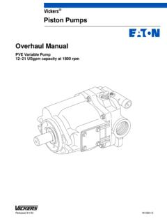
Transcription of Vickers Directional Controls
1 Vickers . Directional Controls Wet Armature Solenoid Operated Directional Control Valves Model DG4V-5, 20 Series Typical Construction of a Spring-Centered DC Valve with Variable Speed Pilot Control passage Speed control orifice plug, optional. See model code description General Description Max. pressure .. 315 bar (4500 psi). Max. flow rates .. Up to 120 L/min (32 USgpm), dependent on spool Mounting surface .. ISO 4401 size 05. NFPA D02. DIN 24340 (NG10). A range of four-port solenoid operated Directional control valves with four-land spool design to facilitate provision of smooth, variable valve response speeds. The range includes: F AC and DC wet-armature solenoid options with ISO 4400 (DIN 43650). electrical connections and manual overrides.
2 F Variable speed changeover potential in all DC models; see Response Times section F Many spool types; in spring-offset, spring-centered and detented arrangements. Functional Symbols Double Solenoid Valves, Single Solenoid Valves, Single Solenoid Valves, Two-Position, Detented Solenoid at Port A End Solenoid at Port B End AB AB A B. Y Y Y. Sol. B Sol. A Sol. B Sol. A. P T PT P TJ. DG4V-5-*N valves DG4V-5-*A valves DG4V-5-*AL valves 2 0 0. 6 2 2. Double Solenoid Valves, Spring Centered 22 22. AB. Y Y 23 23. Sol. B P TJ Sol. A. DG4V-5-*C valves DG4V-5-*B valves DG4V-5-*BL valves 0 0 0. 1 1 1. 2 2 2. 3 3 3. 6 6 6. 7 7 7. 8 8 8. 11 11 11. 31 31. 33 33 31. 34 34. 33. 52 34. 56 52. 521 521 56. 561 561. Y Transient condition only.
3 J Both ports TA and TB are available. Model Code (F13-) DG4V-5-** *(L) (J) (-**)- (V) M- (S6)- U - ** 6- 20- J**. 1 2 3 4 5 6 7 8 9 10 11. 1 Prefix, fluid compatibility 6 Solenoid energization identity For Mounting Subplates and Fixing Blank = AC or DC-voltage models for V = Solenoid A is at port A end Bolt Kits petroleum oils, water-in-oil and/or solenoid B is at port B See catalogs 2425 and 2314. (invert) emulsions or end, independent of spool type For Electrical Plug(s). phosphate esters. Omit for US ANSI standard See end of Installation Dimensions . AC-voltage models for water requiring solenoid A to connect P to A. section. glycols. when energized and/or solenoid B to F13 = DC-voltage models for water connect P to B.
4 Glycols. Operating Data 7 Spool position indicator switch Max. Pressures 2 Spool type Ports P, A and B .. 315 bar (4500 psi). S6 - LVDT type DC switch with Pg7. Ports TA and TB .. 120 bar (1750 psi). See Functional Symbols section connector plug for AC sol. 160 bar (2325 psi). 3 Spool spring arrangement 8 Electrical connection(s) for DC sol. A = Spring-offset, end-to-end U = ISO 4400 (DIN 43650). AL = As A but left-hand build mounting(s) without plug(s) Control Data B = Spring offset, end-to-center BL = As B but left-hand build 9 Coil rating For coil ratings see 8 in Model Code . C = Spring centered section. A = 110V AC 50. N = Two-position, detented C = 220V AC 50 Power Consumption See also Functional Symbols section ED = 240V AC 50 AC Solenoids EK = 115V AC 60.
5 4 Spool design EH = 230V AC 60 AC AC. J = All DC valves except 0A G = 12V DC 50 Hz 60 Hz spool/spring arrangements. H = 24V DC Inrush, max. YVA 700 750. AC valves with 8B(L) and 8C HL = 24V DC (32W) Steady-state BVA 375 440. spool/spring arrangements. OJ = 48V DC Holding VA 105 130. Omit for 0A DC-valves and all AC P = 110V DC. valves except 8B(L) and 8C All above values are RMS. spool/spring arrangements Y Armature fully retracted, 1st half-cycle. 10 Design number, 20 series B At start of normal working stroke of valve Subject to change. Installation spool. Previously called Inrush . 5 Manual override option dimensions unaltered for design P = Standard overrides in both ends numbers 20 to 29 inclusive DC Solenoids of single-solenoid valves At rated voltage and wire temperature of H = Water-resistant override(s) in 20_C (68_F): 11 Spool speed control solenoid end(s)B Type HL.
6 32W. J06 = 0,6 mm orifice Others .. 38-42W. H2 = Water-resistant overrides in both J08 = 0,8 mm orifice ends of single-solenoid valves J10 = 1,0 mm orifice Z = No overrides at either end J12 = 1,2 mm orifice Omit for standard plain override(s) in J99 = no orifice. Must be specified solenoid end(s) onlyB where future fitting of orifice is required, B No override in non-solenoid end of see page , Spool Speed Control single-solenoid valves. Orifice . Performance Data Pressure Drops Typical with petroleum oil at 36 cSt (170 SUS) and a specific gravity of 0,87. psi bar psi bar 16 8 225. 10 3000 11. 200 14 200 12. 9. 7 2500 175. Pressure drop 12. Pressure drop 6 150. 150 10 5 2000. 125. 8 4. 100 3 1500 100. 6 2. 1 75.
7 1000. 4. 50 50. 2 500. 25. 0 0. 0 20 40 60 80 100 120 L/min 0 20 40 60 80 100 120 L/min 0 5 10 15 20 25 30 US gpm 0 5 10 15 20 25 30 US gpm Flow rate Flow rate Spool/spring code Spool positions P to A P to B A to T B to T P to T A to B or covered B to A. 0A(L) Both 2 2 4 5 . 0B(L) & 0C De-energized 3Y . Energized 1 1 6 7 . 1B(L) & 1C De-energized 6B . Energized 1 2 6 4 . 2A(L) Both 3 3 5 6 . 2B(L) & 2C All 2 2 4 5 . 2N Both 3 3 5 6 . 3B(L) & 3C De-energized 5 . Energized 2 3 6 5 . 6B(L) & 6C De-energized 5F 6B . Energized 3 3 6 7 . 6N Both 4 4 4 5 . 7B(L) & 7C De-energized 3F 3B 5g Energized 2 2 5 6 . 8B(L) & 8C All 2 2 7 8 8 . 11B(L) & 11C De-energized 6F . Energized 2 1 4 7 . 22A(L) Both 3 3 . 23A(L) Both 3 3 5 6.
8 31B(L) & 31C De-energized 6 . Energized 3 2 4 7 . 33B(L) & 33C De-energized 12F 12B . Energized 2 2 5 6 . 34B(L) & 34C De-energized 11F 11B . Energized 2 2 5 6 . 52BL & 52C All 7F 8 4 9g 56BL & 56C De-energized 8F 10B . Energized 7F 8 6 9g 521B & 521C All 8 7B 5 9g 561B & 561C De-energized 10F 8B . Energized 8 7B 7 9g Y A and B blocked B A blocked F B blocked g P blocked Operating Data Spool Position Indicator Models Spool/spring arrangement types 0A (L), 2A(L), 22A(L). DC model type S6 . This product has been designed and tested to meet specific standards outlined in the European Electromagnetic Compatibility Directive (EMC) 89/336/EEC, amended by 91/263/EEC, 92/31/EEC and 93/68/EEC, article 5. For instructions on installation requirements to achieve effective protection levels see this leaflet and the Installation Wiring Practices for Vickers Electronic Products leaflet 2468.
9 Wiring practices relevant to this Directive are indicated by Electromagnetic Compatibility (EMC) . Input: Supply voltage 10 to 35V DC inclusive of a maximum 4V pk-to-pk ripple Current, switch open 5 mA. Current, switch closed 255 mA. Output: Voltage 1V below input at maximum load Maximum continuous current 250 mA. Maximum load impedance 136 at maximum input volts Maximum switching frequency 10 Hz Plug connections: Pin 1 (output 1) Normally open (ie. not connected to pin 3). Pin 2 Supply +ve Pin 3 0V. Pin 4 (output 2) Normally closed (ie. connected to pin 3). Switching point Within the spool spring offset condition D. Connector Pg7 plug (supplied with valve). Protection Overload and short-circuit protected; self re-setting.
10 IEC 144 class IP65 with connector correctly fitted. D Factory setting ensures this condition under all combinations of manufacturing tolerance and of temperature drift (see Temperature Limits ) . Wiring Connections Warning All power must be switched off before connecting or disconnecting any plugs. Electrical Panel LVDT Solenoid Customer's protective ground connection WARNING: Electromagnetic Compatibility (EMC). It is necessary to ensure that the unit is wired up in accordance with the connection arrangements shown above. For effective protection the user's electrical cabinet, the valve subplate or manifold and the cable screens should be connected to efficient ground points. In all cases both valve and cable should be kept as far away as possible from any sources of electromagnetic radiation such as cables carrying heavy current, relays and certain kinds of portable radio transmitters, etc.