Transcription of Vickers Pressure Relief - Vickers伊顿威格士-液压
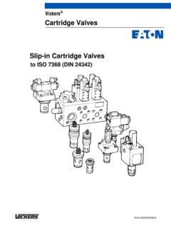
1 R , UR , and X 03/06/10/12 SeriesPressures to 210 bar (3000 psi) Flows to 284 l/min (75 USgpm)686 Released 7/94 Counterbalance, and Reducing ValvesSequence, Unloading, Back Pressure , Vickers Pressure Relief2 Introduction R Series Sequence,Unloading, BackPressure, andCounterbalance ValvesThere are several configurations of thisbasic valve which can be made bychanging cover positions. The followingoutlines each type of and UnloadingVickers Hydrocushion type pressurecontrol valves are used for the control ofunloading and sequence of oil flow inhydraulic systems, induced by apressure rise, directly or by remotemeans. They are available in thefollowing types: sequence valve, Type2 directly operated; sequence valve,Type 3 remotely controlled; unloadingvalve, Type 4 remotely PressureBack Pressure valves are designated asType 1 internally operated.
2 They areused to provide back Pressure on thehydraulic actuator to preventoverrunning. A remote P version is alsoavailable for use in braking Hydrocushion typecounterbalance valves are used for thecontrol of unloading and sequence of oilflow in hydraulic systems, induced bypressure rise either directly or by remotemeans. They are available in thefollowing types: counterbalance valve,Type 1 internally operated;counterbalance valve, Type 4 remotelycontrolled. These valves are usuallyapplied in a system to keep a verticalload from falling. All models provide freereverse flow by means of an integralcheck valve. (Refer to valves withoutintegral check when reverse free flow isnot required.)
3 UR Series UnloadingRelief valves withIntegral Check ModuleAn integral check valve prevents returnflow from the accumulator through theunloading valve. In an accumulatorsystem, the valve cuts out automaticallywhen the accumulator Pressure reachesadjusted maximum. At cut-in Pressure (approximately 85% of adjustedmaximum), the valve directs delivery tothe accumulator and the hydraulicsystem a double pump system, the valveautomatically sequences the pumps todeliver a large volume of oil at lowpressure and a small volume of oil athigh designated URT have threadedports and require a separate checkvalve to function as an unloading circuit. X Series PressureReducing ValvesThese Pressure reducing valvesmaintain a reduced level of outletpressure regardless of variations in inletpressure above the Pressure setting ofthe valve.
4 The valves also allow reversefree flow at pressures below the settingof the of ContentsSeries R(C)*-03/06/10/12 Sequence, Unloading, Back Pressure , and Counterbalance Valves3.. Series URT*-06/10 Unloading Relief Valves14.. Series URG*-06/10 Unloading Relief Valves17.. Series XSL/XTL-03 Pressure Reducing Valves21.. Series XGL-03 Pressure Reducing Valves23.. Series X(C)*-03/06/10 Pressure Reducing Valves26.. Application Data35.. 3 Series R(C)*-03/06/10/12 Sequence, Unloading,Back Pressure , and Counterbalance ValvesRatingsRated Pressure (Maximum)*210 bar (3000 psi)Rated Capacity (Maximum)**R*-03R*-06R*-10 and R*-1245 l/min (12 USgpm)114 l/min (30 USgpm)284 l/min (75 USgpm)* 140 bar (2000 psi) permitted on the full piston area at the bottom cover ( P connection),and at the top cover (spring chamber).
5 See tank drain information on page 4.** Rated capacities are based on using fluid with a specific gravity of and a viscosity of20 cSt (100 SUS).Special sealsF3 For mineral oil and fire resistantfluids. Mounting face seals ofRCG model are standardBuna-N unless specified as Omit for standard, R(C)S, andR(C)T typeR Pressure control valveIntegral check valveC Reverse free flow checkConnectionsG Manifold or subplate mountingS SAE straight threadT NPTF thread**Not recommendedRemote control connectionP Auxiliary remote pressurecontrol connection (notavailable with X, Y, or Zpressure ranges or inR(C)G-03 models)Blank Omit if not requiredValve application type1 Internal drain directly operated2 External drain directly operated3 External drain remotely operated4 Internal drain remotely operatedDesign numberSubject to change.
6 Installation dimensionssame for designs 30 through size03 3/8 pipe or UNF-2 Bstraight thread ( tubing)06 3/4 pipe or UN-2 Bstraight thread ( tubing)10 11/4 pipe or UN-2 Bstraight thread ( tubing)12 11/2 pipe or UN-2 Bstraight thread ( tubing)(not available in R(C)G models) Pressure rangeX 0,7 to 2,1 bar (10 to 30 psi)Y 2,1 to 4,1 bar (30 to 60 psi)Z 4,1 to 8,5 bar (60 to 125 psi)A 5,2 to 17,2 bar (80 to 250 psi)B 8,5 to 35 bar (125 to 500 psi)D 17,2 to 70 bar (250 to 1000 psi)F 35 to 140 bar (475 to 2000 psi)345876912 Model Code1234567894 Series R(C)*-03/06/10/12 Sequence, Unloading,Back Pressure , and Counterbalance ValvesGeneral DataVickers hydrocushion type pressurecontrol valves are used to control thesequencing, unloading, back Pressure ,and counterbalancing of oil flow inhydraulic systems.
7 Control is initiated bya Pressure rise which can be sensedeither internally (directly) or are available with or withoutintegral reverse free flow AdjustmentPressure ranges (see model codepage 3) are maximum controllable, andeach model selected should be wellwithin the range given to afford fineincrements of adjustment. Pressuresetting must be at least 17 bar (250 psi)lower than the system Relief valve can be adjusted by looseninga jam nut and turning an adjustmentscrew. Turning clockwise increasespressure, and turning counterclockwisedecreases DataMountingBecause all R(C)T and R(C)S modelshave optional Pressure inlets connectedby a through passage, the valves may bemounted in-line.
8 The valves may also beteed to a line by using either one of thepressure inlets and plugging the remote Pressure control connectionon type 3 and 4 valves must beconnected to an external pilot pressuresource sufficient to operate the valve atthe desired Pressure setting and Drain The discharge outlet of valve types 1 and4 must be piped to tank at atmosphericpressure. The drain connection on types2 and 3 must be piped directly to tank atatmospheric Pressure . Any Pressure atthe drain port must be added to thepressure setting of the Remote PressureControl P All models (except R(C)G -03 and thosewith an X , Y , or Z pressureadjustment range in their model code)are available with an auxiliary remotecontrol connection.
9 Required pressureat the auxiliary connection is 1/16 of thenormally required control Pressure forthe F Pressure range and 1/8 of thenormally required control Pressure forthe A , B , and D Pressure ranges.(This applies to -22 design and up.)Brake ValveA brake valve is used in the exhaust lineof a hydraulic motor to: 1) preventoverspeeding when an overrunning loadis applied to the motor shaft; and 2)prevent excessive Pressure buildupwhen decelerating or stopping a the RC valve is used as a brakevalve, it has a solid spool (no drain holethrough the center), and there is aremote operating Pressure connection inthe bottom cover directly under the connection is teed into the supplyline to the motor.
10 The internal controlconnection is also used under the smallpiston and senses Pressure from theprimary port of the RC valve, which isconnected to the motor exhaust the load is being accelerated, Pressure is maximum at the motor inletand under the large area of the brakevalve spool, holding it in the full openposition and permitting free flow fromthe exhaust port of the the motor gets up to speed, loadpressure still holds the brake valve openunless the load tries to run away. If thishappens, the Pressure falls off at the motorinlet and in the remote control pressurepassage. The spring force tends to closethe valve, thus increasing the backpressure on the motor, tending to brake the directional valve is shifted toneutral, inertia may cause the motor tocontinue rotating against the brake the motor stops turning, it willoperate as a pump, drawing fluid fromthe motor outlet through the directionalvalve and circulating it back to the motorinlet.