Transcription of VSR - US Alarm & Detection Supply | Fire, Alarm, …
1 PRINTED IN USA PAGE 1 OF 3 VSRVANE TYPE WATERFLOWALARM SWITCH WITH RETARDMFG. #5401146 - REV H 12/07 General InformationThe Model VSR is a vane type waterfl ow switch for use on wet sprinkler systems. It is UL Listed and FM Approved for use on steel pipe; schedules 10 through 40, sizes 2" thru 8" (50 mm thru 200 mm).LPC approved sizes are 2" thru 8" (50 mm thru 200 mm). See Ordering Information VSR may also be used as a sectional waterfl ow detector on large VSR contains two single pole, double throw, snap action switches and an adjustable, instantly recycling pneumatic retard. The switches are actuated when a flow of 10 GPM (38 LPM) or more occurs downstream of the device. The fl ow condition must exist for a period of time necessary to overcome the selected retard The VSR switches and retard device are enclosed in a general purpose, die-cast housing.
2 The cover is held in place with two tamper resistant screws which require a special key for removal. A fi eld installable cover tamper switch is available as an option which may be used to indicate unauthorized removal of the cover. See bulletin number 5401103 for installation instructions of this : See Fig. 1 These devices may be mounted on horizontal or vertical pipe. On horizontal pipe they should be installed on the top side of the pipe where they will be accessible. The device should not be installed within 6" (15 cm) of a fi tting which changes the direction of the waterfl ow or within 24" (60 cm) of a valve or the system and drill a hole in the pipe using a hole saw in a slow speed drill.
3 (see Fig. 1)Clean the inside pipe of all growth or other material for a distance equal to the pipe diameter on either side of the the vane so that it may be inserted into the hole; do not bend or crease it. Insert the vane so that the arrow on the saddle points in the direction of the waterfl ow. Install the saddle strap and tighten nuts alternately to required torque. (see Fig. 1). The vane must not rub the inside of the pipe or bind in any cations subject to change without Electric Signal Company 2081 Craig Road, St. Louis, MO, 63146-4161 Phone: 800-325-3936/Canada 888-882-1833 , CUL and CSFM Listed, FM Approved, LPCB Approved, For CE Marked (EN12259-5) / VdS Approved model use VSR-EU Service Pressure: 450 PSI (31 BAR) - UL Flow Sensitivity Range for Signal: 4-10 GPM (15-38 LPM) - UL Maximum Surge: 18 FPS ( m/s)Contact Ratings: Two sets of SPDT (Form C) Amps at 125/250 VAC Amps at 30 VDC Resistive 10 mAmps min.
4 At 24 VDCC onduit Entrances: Two knockouts provided for 1/2" conduit. Individual switch compartments suitable for dissimilar Specifi cations: NEMA 4/IP54 Rated Enclosure suitable for indoor or outdoor use with factory installed gasket and die-cast housing when used with appropriate conduit fi tting. Temperature Range: 40 F - 120 F, ( C - 49 C) - UL Non-corrosive sleeve factory installed in Use: Automatic Sprinkler NFPA-13 One or two family dwelling NFPA-13D Residential occupancy up to four stories NFPA-13R National fire Alarm Code NFPA-72 Optional: Cover Tamper Switch Kit, Stock No. 0090148 Installation must be performed by qualifi ed personnel and in accordance with all national and local codes and ordinances. Shock hazard. Disconnect power source before servicing.
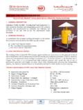
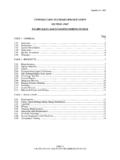
5 Serious injury or death could result. Risk of explosion. Not for use in hazardous locations. Serious injury or death could InformationNominal Pipe SizeModelPart Number2"DN50 VSR-211444022 1/2"DN65 VSR-2 1/211444253"DN80 VSR-311444033 1/2"-VSR-3 1/211444354"DN100 VSR-411444045"-VSR-511444056"DN150 VSR-611444068"DN200 VSR-81144408 PRINTED IN USAMFG. #5401146 - REV H 12/07 PAGE 2 OF 3 VSRVANE TYPE WATERFLOWALARM SWITCH WITH RETARDTo remove knockouts: Place screwdriver at inside edge of knockouts, not in the : 1. The Model VSR has two switches, one can be used to operate a central station, proprietary or remote signaling unit, while the other contact is used to operate a local audible or visual A condition of LPC Approval of this product is that the electrical entry must be sealed to exclude For supervised circuits see Switch Terminal Connections drawing and caution note (Fig.)
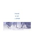
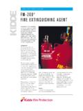
6 2). OUTGOINGINCOMINGDWG# 923-3 Fig. 2 Switch Terminal Connections Clamping Plate TerminalBreak out thin section of cover when wiring both switches from one conduit # 1146-4 WATERFLOWDIRECTION OFTIGHTEN NUTSALTERNATELY MOUNT ON PIPE SOARROW ON SADDLEPOINTS IN DIRECTIONOF WATERFLOWROLL PADDLE IN OPPOSITE DIRECTIONOF WATERFLOWDWG. #1146-1 EDO NOT LEAVE COVER OFF FOREXTENDED PERIOD OF TIMERETARD ADJUSTMENT:THE DELAY CAN BE ADJUSTED BY ROTATING THE RETARD ADJUSTMENT KNOB FROM 0 TO THE MAX SETTING (60-90 SECONDS). THE TIME DELAY SHOULD BE SET AT THE MINIMUM REQUIRED TO PREVENT FALSE ALARMS. COVER TAMPER SWITCHADAPTERUSE (2) 5180162 ADAPTERS AS SHOWN ABOVE DN50 ONLYADAPTER50mm20mm 2mm # 1146-1 FInstallation RequirementsModelNominal Pipe SizeNominal Pipe SizeU-Bolt Nuts + .125 1/22 1/2 1/22 1.
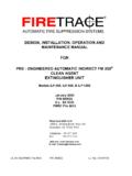
7 1/23 1/2 (Flowing water activates device in one direction only.)DWG# 1146-5 DWG# 1146-3 APOSITIVE DC OR HOT ACNEGATIVE DC OR NEUTRAL ACWATERFLOW ZONE ON fire PANELBELLEOLR NO NC COMCOM NC NOFig. 1An uninsulated section of a single conductor should not be looped around the terminal and serve as two separate connections. The wire must be severed, thereby providing supervision of the connection in the event that the wire become dislodged from under the terminal. Failure to sever the wire may render the device inoperable risking severe property damage and loss of ow switches that are monitoring wet pipe sprinkler systems should not be used as the sole initiating device to discharge AFFF, deluge, or chemical suppression systems. Waterfl ow switches used for this application may result in unintended discharges caused by surges, trapped air, or short retard 3 Typical Electrical ConnectionsFig.
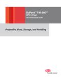
8 4 Fig. 5 PRINTED IN USA PAGE 3 OF 3 VSRVANE TYPE WATERFLOWALARM SWITCH WITH RETARDMFG. #5401146 - REV H 12/07141,2 mm ( )50,8 mm( )GROUND SCREWS89,0 mm ( )PIPE DIA.+133,4 mm(+ 5-1/4 )59,4 mm( )U-BOLT NUTU-BOLT WASHERPIPE SADDLEPIPEPLASTIC PADDLEU-BOLTNOMINAL PIPE DIA. +44,5 mm (+ 1-3/4) FOR DN50 - DN65 (2 - 2-1/2 )NOMINAL PIPE DIA. +54,0 mm (+ 2-1/8 ) FOR DN80 - DN200 (3 - 8 ) DWG# 1146-6 Testing The frequency of inspection and testing for the Model VSR and its associated protective monitoring system should be in accordance with applicable NFPA Codes and Standards and/or the authority having jurisdiction (manufacturer recommends quarterly or more frequently).If provided, the inspector s test valve, that is usually located at the end of the most remote branch line, should always be used for test purposes.
9 If there are no provisions for testing the operation of the fl ow Detection device on the system, application of the VSR is not recommended or minimum fl ow of 10 GPM (38 LPM) is required to activate this detectors monthly for leaks. If leaks are found, replace the detector. The VSR waterfl ow switch should provide years of trouble-free service. The retard and switch assembly are easily fi eld replaceable. In the unlikely event that either component does not perform properly, please order replacement retard switch assembly stock #1029055. There is no maintenance required, only periodic testing and To prevent accidental water damage, all control valves should be shut tight and the system completely drained before waterfl ow detectors are removed or replaced. Turn off electrical power to the detector, then disconnect wiring.
10 Loosen nuts and remove U-bolts. Gently lift the saddle far enough to get your fi ngers under it. With your fi ngers, roll the vane so it will fi t through the hole while continuing to lift the waterfl ow detector saddle. Lift detector clear of NoticePlease advise the person responsible for testing of the fire protection system that this system must be tested in accordance with the testing PipeModelNominal Pipe SizeNominal Pipe Wall ThicknessSchedule 10 (UL)Schedule 40 (UL)BS-1387 (LPC)DN (VDS) 1/22 1 VSR-2 1/2 1/23 1/2 : For copper or plastic pipe use Model NC COMCOM NC NOMounting Dimensions