Transcription of WARNING - firestoneip.com
1 2071. WARNING : Do not inflate this assembly when it is unrestricted. The assembly must be restricted by the suspension or other adequate structure. Do not inflate beyond 100 psi Improper use or over inflation may cause property damage or severe personal injury. This kit will not fit the 1997-current Ford F-150. & 250 light duty pickups under 8500 GVWR. Installation of this kit requires a minimum of 7-1/2" of clearance between the tire side wall and the frame. INSTALLATION INSTRUCTIONS IMPORTANT! Congratulations your new Air Helper Springs are quality For your safety and to prevent possible damage to your products capable of improving the handling and comfort vehicle, do not exceed the maximum load recommended of your vehicle. As with all products, proper installation is by the vehicle manufacturer (GVWR). Although your Air the key to obtaining all of the benefits your kit is capable of Helper Springs are rated at a maximum inflation pressure delivering.
2 Please take a few minutes to read through of 100 psi, this pressure may allow you to carry too great the instructions to identify the components and learn a load on some vehicles. It is best to have your vehicle where and how they are used. It is a good idea to start weighed once it is completely loaded and compare that by comparing the parts in your kit with the parts list below. weight to the maximum allowed. Check your vehicle The heart of the air helper spring kit is, of course, the owner's manual or data plate on driver's side door for air springs. Remember that the air helper springs must maximum loads listed for your vehicle. flex and expand during operation, so be sure that there When inflating your Air Helper Springs, add air pres- is enough clearance to do so without rubbing against any sure in small quantities, checking pressure frequently other part of the vehicle. during inflation.
3 The air spring requires much less air Be sure to take all applicable safety precautions volume than a tire and, therefore, inflates much quicker. during the installation of the kit. The instructions listed in this brochure and the illustrations all show the left, TOOLS REQUIRED. or driver's side of the vehicle. To install the right side (2) 9/16" END WRENCHES ELECTRIC DRILL. assembly simply follow the same procedures. Your kit includes separate inflation valves and air (2) 1/2" END WRENCHES 5/16" DRILL BIT. lines for each air helper spring. This will allow you to UTILITY KNIFE 3/8" DRILL BIT. level your vehicle from side to side as well as from front to back. If you would rather have a single valve inflation system, your dealer can supply the required T fitting. PARTS LIST. 267C AIR SPRING 6781 2 3/8"-16 X 3/4" FLANGE HEX BOLT 2. UPPER BRACKETS 5376 2 3/8"-16 X 7" CARRIAGE BOLTS 8. LOWER BRACKETS 5092 2 3/8" FLAT WASHER 12.
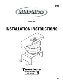
4 BRACKET STRAP/SHIM 1/2" 5086 4 3/8"-16 X 1 1/2 HEX BOLTS 8. BRACKET STRAP/SHIM 1" 5093 4 5/16" FLAT WASHER 4. BRAKE LINE BRACKET 5427 1 PUSH TO CONNECT INFLATION VALVE 2. AIR LINE TUBING 1 PUSH TO CONNECT ELBOW FITTING 2. 3/8"-16 FLANGE LOCK NUT 21 THERMAL SLEEVE 2. 3/8"-16 X 1" HEX BOLT 1 NYLON TIE 6. 21-8258 08-12. 2071. KIT ASSEMBLY. FIGURE A . KIT TO FRAME ASSEMBLY. STEP 1 PREPARE THE VEHICLE. With the vehicle on a solid, level surface chock the front wheels. Raise the vehicle by the rear axle and remove the rear wheels. After the removal Remove any bracket of the wheels lower the vehicle so the axle rests on jack stands rated portion that is not flush for your vehicles weight. Remove any jounce bumper bracket that is not with the frame. Either mounted flush with the frame which will interfere with the operation of the cut it away or unbolt air helper springs see Figure B . Jounce bumpers located under the and remove it.
5 Frame rail may be left in place. This installation assumes that there is no load in the bed of the truck. Remove the negative battery cable. On 2005 and newer Ford vehicles the emergency brake line bracket FIGURE B . must be relocated. Remove the screw holding the brake line. Install the relocating bracket with the screw previously removed. NOTE: the bracket is marked top. Next, fasten the emergency brake line bracket to the relocation bracket using the 3/8" X 1" bolt and a 3/8" nut. STEP 2 PREASSEMBLE THE KIT. Select one air helper spring and an upper bracket from your kit. Align the studs of the air spring with the mounting holes of the upper bracket and insert. Make sure the air inlet is visible through the large access hole in the upper bracket. Fasten the upper bracket to the air spring using the 3/8"-16 flanged lock nuts, see Figure A . Install the elbow fitting into the air spring through the large access hole in the upper bracket.
6 Tighten the air fitting securely to engage the orange thread sealant. Position the fitting to point to the anticipated location of the air inflation valves, see Figure A & E . Select one lower bracket and place the bracket so the lip of the lower bracket will be next to the tire, see Figure A . If you are installing this kit on a 1987 or earlier GMC pickup or a 1994 or DRIVER'S SIDE FRONT. earlier Dodge pickup review notices on Figure A . Fasten the lower bracket using a 3/8"-16 x 3/4" flange hex bolt (finger tight) through the center slot into the threaded hole in the air spring. FIGURE C . STEP 3 PRE-FIT AND MARK / DRILL HOLES. Position the air spring assembly on the leaf spring stack. The lower FORD FRAME ILLUSTRATED. bracket should straddle the leaf spring retainer and the upper bracket mounting flanges should be flush against the frame. Depending on the .. application, the lower bracket may have to be raised ( interference with U -bolts, leaf spring retainer, brake drum, ).
7 This kit comes .. with two sets of bracket straps/shims. These are included to provide . adequate clearance for the air spring and lower bracket, as well as, any . other component on the vehicle. One set is 1/2" tall while the other set is 1" tall. To raise the air spring assembly to its maximum height, install the 1" shim between the lower bracket and the leaf spring stack. The remaining 1/2" strap/shim will be used to clamp the assembly to the leaf spring stack, see Figure D . The bracket straps/shims may be interchanged, or not used, to provide maximum clearance and proper air spring height. Furthermore, the shims can be mixed ( use the 1/2" on one side and the 1" or none on the other) to adjust for leaf spring slant. FIGURE "D". Once the height of the lower bracket has been established, adjust the position of the upper bracket so that the mounting flanges are flush with the side of the frame rail .
8 To do this, slide the air spring over the lower bracket along its slotted connection. With the brackets now AIR AIR HOSE. SPRINGS. positioned properly and the air spring in proper alignment, tighten the 3/8"-16 x 3/4" hex bolt securing the lower bracket to the air spring. It may be necessary to slide the entire assembly fore or aft along the leaf spring in order to provide clear mounting. Before marking and drilling the holes for the upper bracket, make sure the mounted height of the air spring is between " - 6-1/2", that there is at least 1-1/2" between INFLATION. the edge of the hole and the inside of the upper and lower frame flange VALVES. , and the upper and lower brackets are as parallel as possible,see Figure "D". Mark the four holes to be drilled with a center punch using BUMPER. the upper bracket as a template, then remove the air spring assembly. FIGURE E . Before drilling the holes make sure all electrical, brake and fuel lines are cleared from the path of the drill.
9 Damage to lines can be avoided by inserting a piece of wood between the frame rail and any lines in the path of the drill. Drill the four holes in the frame rail using a 3/8" drill bit, see Figure A . STEP 4 INSTALLATION TO THE VEHICLE AIR LINE. After drilling the holes in the frame rail place the assembled air spring back on the leaf stack making sure the lower bracket is placed over the FLAT WASHER. retainer, see Figure A & C . Check to see Ford trucks that there is a 1/2" of clearance between the air spring and the emergency brake line bolt, this bolt may have to be cut down for clearance. Install the 3/8"-16 x PUSH-TO-CONNECT. 1 1/2" hex bolts through the upper bracket holes and the holes that were INFLATION VALVE. drilled in the frame rail . Next fasten the upper bracket to the frame rail BODY OF. using the 3/8"-16 flange lock nuts and flat washers to the back side of VEHICLE. the frame rail , refer to Figure A.
10 The next step is to attach the lower bracket to the leaf spring assembly. Use the bracket strap/shim that is HEX NUT. VALVE CAP. not being used as a spacer or 1/2" spacer/shim if no spacer is required, FIGURE F . and fasten the air spring assembly to the leaf stack using the 3/8"-16 x 7" carriage bolts and 3/8"-16 flanged lock nuts, see Figure A . NOTE: You may clamp around the over-load leafs. Insert the carriage bolt through the inner square hole on the lower bracket for narrow leaf springs. STEP 5 INSTALLATION TO THE PASSENGER'S SIDE ASSEMBLY. Reverse any orientations when assembling and installing the right, or passenger, side of the vehicle. STEP 6 INSTALL THE AIR LINE AND THE INFLATION VALVE. Uncoil the air line tubing and cut it into two equal lengths. DO NOT FOLD OR KINK THE TUBING. Try to make the cut as square as possible. Insert one end of the tubing into the elbow fitting installed in the top of the air helper spring.