Transcription of Water Level Controlling System Using Pid Controller
1 International Journal of Applied Engineering Research ISSN 0973-4562 Volume 11, Number 23 (2016) pp. 11223-11227. Research India Publications. Water Level Controlling System Using Pid Controller Beza Negash Getu Department of Electrical, Electronics and Communications Engineering (EECE). American University of Ras Al Khaimah, Ras Al Khaimah, UAE. ABSTRACT and simplicity in Controlling aspects [6]. The DC motor is a In certain applications such as chemical and industrial highly controllable electrical actuator and is widely used for processes, it is important to keep the Level of Water or any robotic manipulators, guided vehicles, steel rolling mills, other liquid in a tank or similar container at a certain desired cutting tool, overhead cranes, electrical traction and other Level . In this work, we present PID based Controller System applications.
2 In comparison to AC drive, DC motor drives are where the Level of Water is controlled by adjusting the rate of simple and less expensive [6], [7]. In certain applications, the the incoming Water flow to the container by varying the speed Water , which could also be any other liquid in an industrial or of a DC motor Water pump that is filling the container. The chemical process need to be carefully supplied and kept at a accuracy of the PID based Controlling is demonstrated Using certain Level in the storage System . The intention of the MATLAB simulation software. Controlling the Level in the storage is to achieve a perfect process control and as a result increase efficiency and Keywords- Water Level , flow rate, tank, DC motor speed, productivity. A PID control theory and feedback System feedback control, proportional integral derivative (PID).
3 Modelling is applied to design the overall System . As a result of maintaining the required Water set Level , the System not only increases process productivity but also assists towards INTRODUCTION saving and conserving Water by monitoring the Level and Water is an essential natural resource, which is vital not only eliminating overflow in the storage System . to sustain life for drinking purposes but also used in many industrial, chemical, commercial and agricultural processes. The improper use and management of Water affects the System MODEL. sustainability of our environment. Among others in The proposed System comprises a DC motor Water pump that agricultural areas, Water pumps need to be controlled in order pumps Water to the container, the PID Controller and a Water to supply regulated Water for the plantations or farm lands. tank or any other storage System .
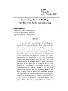
4 Consider the diagram in Controlled Water can be given by designing automatic Fig. 1 where the motor pumps Water to the container at a rate electronic control systems as studied in [1], [2]. On the other of qin [m3/s] through an inlet pipe, the container with cross- hand, in chemical or industrial processes such as treatment of sectional area A[in m2], is filled to Water Level , h and Water is Water in desalination plants, the Level of Water in a container leaving the container at a rate of qo [m3/s] through an outlet like a tank need to be kept at certain set desired point. The pipe. Using the balance of the flows into and out of the tank, Level of the Water need to be maintained at the desired set the height, h is related to qin and qo as [8]: point for the proper functioning of the process and achieve the dh desired target or product. In this case, a Controlling System qin q0 A (1).
5 Such as proportional-integral and derivative (PID) Controller dt plays a significant role in maintaining the accurate Level by The out flow from the tank and the height can also be related implementing the System in a feedback control System . PID assuming linear resistance to flow for simplicity of analysis controllers are used in most practical control systems ranging and it is given as: from consumer electronics such as cameras to industrial h q0 (2). processes such a chemical processes [3]-[5]. The PID Rf Controller helps to get our desired output, which could be velocity in moving objects, temperature in particular Where Rf [in s/m2] is the flow resistance. environment, position at certain location, liquid Level in a container and etcetera where we want to achieve a certain set point in a short possible time with minimal overshoot and with little steady state error.
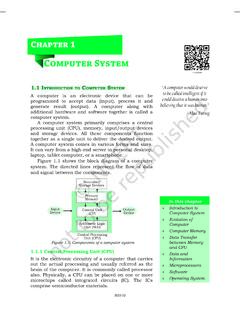
6 The performance of the PID qin Controller are also determined by overshoots, rising time, settling time and steady state error parameters. pump In this work, we assumed a DC motor Water pump filling a h Water certain Water container or tank and the speed of the motor determines the rate of Water flow to the tank. The DC motors qo are used extensively in industries due to their variable speed that suits them to be used for different applications, their most A. demanding speed-torque characteristics and their reliability Figure 1. Single Tank container filled to Level h. 11223. International Journal of Applied Engineering Research ISSN 0973-4562 Volume 11, Number 23 (2016) pp. 11223-11227. Research India Publications. The overall System is a feedback control System as shown in R L. the block diagram given in Fig. 2. Firstly, a reference input height Level , h0(t), is set that shows the desired Level the tank T.
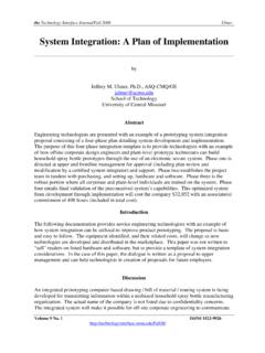
7 Has to be filled. In the forward path, we have the PID +. V. Controller that controls the speed of the DC motor. The speed i of the motor is directly related to the Water flow rate qin e K e J. supplying the tank. At the output of the overall System , we armature circuit - rotor have the Water Level , h(t) and this information is feedback at b . the input and compared with the reference desired Level . The error signal between the actual output and the reference, e(t). will be an input signal to the PID Controller and the speed of Figure 3. Equivalent circuit of the DC motor the motor [ (t) in rad/s] will be adjusted (either increased or decreased) to control the flow rate qin until the required target Using the properties of Laplace transform, the above Water Level is achieved. The speed information of the motor is equations can be expressed in the Laplace or s' domain as assumed to be obtained from speed measurement device such [10]: as tachometer.
8 The speed will be transformed by the speed to s 2 J (s) sb (s) Kt I (s) (6). height transformation (STH) block that relates the speed to the flow rate and then to the Water Level h(t). For simplicity purposes of the study, we assume a simple linear relationship sLI (s) RI (s) V (s) sKe (s) (7). between the speed and the incoming flow rate to the tank given as: The angular speed in the Laplace domain is related to the (t ) K f qin (t ) (3) angular position as (s)= s (s) and hence can be substituted in the above equations. By eliminating the current I(s) in (6) and (7) and after some steps, the motor rotational speed output, h0 ( t ) e (t ) v (t ) (t ) (s), is related to the armature voltage input, V(s), as: PID Motor STH h (t ).. Controller pump ( s) Kt Pm ( s) (8). V ( s) s JL s( JR bL) Rb Kt K e 2. The relation in (8) represents the input output relations of the Figure 2.
9 Block diagram of the Water Level Controlling System motor-pump block shown in Fig. 2. The PID Controller is the other part of the System as shown in MODELING THE MOTOR PUMP AND THE PID The job of the PID Controller is to adjust the output, in Controller this case the Water Level at the desired set point so that in the The Water pump is a DC motor with the electric equivalent ideal case there is no error between the sensed output, h(t), circuit of the armature and the free-body diagram of the rotor as and the desired reference Level . In general design of the PID, shown in Fig. 3 [9]. The input to the motor is a voltage source the error e(t) is related to the output v(t) as [11]: (V) applied to the motor's armature, the output is the rotational speed of the shaft (t) =d /dt. The rotor and shaft are assumed de(t ). to be rigid. We further assume a viscous friction model, that is, v(t ) K p e(t ) Ki e(t ) K d (9).
10 The friction torque is proportional to shaft angular velocity. The dt physical parameters of the motor are J: moment of inertia of the rotor [ ], b: motor viscous friction constant [in ], Where Kp, Ki and Kd are called the proportional gain, the Ke: electromotive force constant [in V/rad/sec], Kt: motor integral gain and the derivative gain respectively. The torque constant [in ], R: electric resistance [in ]. L: proportional gain provides an overall control action electric inductance [in H]. Assuming armature controlled proportional to the error signal, the integral gain action is to motor, the torque is proportional to the armature current reduce steady-state errors through low-frequency (T=Kti) and the back emf is proportional to the angular compensation by an integrator and the derivative gain velocity of the shaft, e=Ke . Using the above facts and based improves transient response through high-frequency on Newton's second law and Kirchhoff's voltage law, the DC compensation by a differentiator.