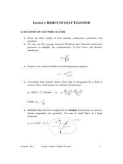
Transcription of Week 13 Chapter 10 Combined Power Cycles
1 1 Week 13 Chapter 10 Vapor & Combined Power CyclesMECH341: Thermodynamics of Engineering SystemThe Carnot vapor cycleT-s diagram of two Carnot vapor Carnot cycle is the most efficient cycle operating between two specified temperature limits but it is not a suitable model for Power Cycles . Because: Process 1-2 Limiting the heat transfer processes to two-phase systems severely limits the maximum temperature that can be used in the cycle (374 C for water) Process 2-3 The turbine cannot handle steam with a high moisture content because of the impingement of liquid droplets on the turbine blades causing erosion and wear. Process 4-1It is not practical to design a compressor that handles two cycle in (b) is not suitable since it requires isentropic compression to extremely high pressures and isothermal heat transfer at variable isothermal heat addition in a boiler 2-3 isentropic expansion in a turbine 3-4 isothermal heat rejection in a condenser4-1 isentropic compression in a compressor2 Rankine cycle: The ideal cycle for vapor Power Cycles Many of the impracticalities associated with the Carnotcycle can be eliminated by superheating the steam in theboiler and condensing it completely in the condenser.
2 The cycle that results is the Rankine cycle, which is theideal cycle for vapor Power plants. The ideal Rankinecycle does not involve any internal simple ideal Rankine : Only slight change in water temp through pump The steam generator consists of boiler (two-phaseheat transfer) and superheater turbine outlet is high-quality steam Condenser is cooled by water (eg. lake, river,cooling tower) or by air (when water is scarce)Thermal analysis of the Ideal RankineCycleThe thermal efficiency can be interpreted as the ratio of the areaenclosed by the cycle on a T-s diagram to the area under the heat-addition energy equation3 Deviation of actual vapor Power Cycles from idealized ones(a) Deviation of actual vapor Power cycle from the ideal Rankine cycle. (b) The effect of pump and turbine irreversibilities on the ideal Rankine cycle. The actual vapor Power cycle differs from the ideal Rankine cycle as a result ofirreversibilities in various components.
3 Fluid frictionandheat loss to the surroundingsare the two common sources efficienciesExample steam enters the turbines of both a Carnot and a simple ideal Rankine Cycles in both cases at 5 Mpa as saturated vapor, and the condenser pressure is 50 kPa. In the Rankine cycle, the condenser exit state is saturated liquid and in the Carnot cycle, the boiler inlet state is saturated liquid. Draw the T s diagrams in both Cycles . Determine the net work output and the thermal efficiency for the Carnot and the simple ideal Rankine min. BreakHow can we increase the efficiency of the Rankine cycle?The effect of lowering the condenser pressure on the ideal Rankine basic idea behind all the modifications to increase the thermal efficiencyof a Power cycle is the same:Increase the average temperature at which heat istransferred to the working fluid in the boiler, or decrease the average temperature atwhich heat is rejected from the working fluid in the Lowering the Condenser Pressure (Lowers Tlow,avg) To take advantage of the increased efficiencies at low pressures, the condensers of steam Power plants usually operate well below the atmospheric pressure.
4 There is a lower limit to this pressure depending on the temperature of the cooling medium Side effect: Lowering the condenser pressure increases the moisture content of the steam at the final stages of the can we increase the efficiency of the Rankine cycle?The effect of superheating the steam to higher temperatures on the ideal Rankine Superheating the steam to High Temperatures (Increases Thigh,avg) Both the net work and heat input increase as a result of superheating the steam to a higher temperature. The overall effect is an increase in thermal efficiency since the average temperature at which heat is added increases. Superheating to higher temperatures decreases the moisture content of the steam at the turbine exit, which is desirable. The temperature is limited by metallurgical considerations. Presently the highest steam temperature allowed at the turbine inlet is about 620 can we increase the efficiency of the Rankine cycle?
5 103. Increasing the Boiler Pressure (Increases Thigh,avg)The effect of increasing the boiler pressure on the ideal Rankine a fixed turbine inlet temperature, the cycle shifts to the left and the moisture content of steam at the turbine exit increases. This side effect can be corrected by reheating the supercritical Rankine many modern steam Power plants operate at supercritical pressures (P > MPa) and have thermal efficiencies of about 40% for fossil-fuel plants and 34% for nuclear ideal reheat Rankine cycleHow can we take advantage of the increased efficiencies at higher boiler pressureswithout facing the problem of excessive moisture at the final stages of the turbine ?1. Superheat the steam to very high temperatures. It is limited Expand the steam in the turbine in two stages, and reheat it in between (reheat)The ideal reheat Rankine reheat stages Rankine cycleThe average temperature at which heat is transferred during reheating increases as the number of reheat stages is increased.
6 The single reheat in a modern Power plantimproves the cycle efficiency by 4 to 5%by increasing the average temperature atwhich heat is transferred to the steam . The average temperature during the reheatprocess can be increased by increasing thenumber of expansion and reheat stages. Asthe number of stages is increased, theexpansion and reheat processes approachan isothermal process at the maximumtemperature. The use of more than improvement in efficiencyfrom the second reheat is about half ofthat which results from a single reheat. The reheat temperatures are very close orequal to the turbine inlet temperature. The optimum reheat pressure is about one-fourth of the maximum cycle ideal regenerative Rankine cycleThe first part of the heat-addition process in the boiler takes place at relatively low temperatures. Heat is transferred to the working fluidduring process 2-2 at a relatively lowtemperature.
7 This lowers the average heat-addition temperature and thus the cycleefficiency. In steam Power plants, steam is extractedfrom the turbine at various points. Thissteam, which could have produced morework by expanding further in the turbine ,is used to heat the feedwater instead. Thedevice where the feedwater is heated byregeneration is called a regenerator, or afeedwater heater (FWH). A feedwater heater is basically a heatexchanger where heat is transferred fromthe steam to the feedwater either by mixingthe two fluid streams (open feedwaterheaters) or without mixing them (closedfeedwater heaters).The ideal regenerative Rankine cycle with Open Feedwater Heater (OFWH)An open(or direct-contact) feedwater heateris basically a mixing chamber, where the steam extracted from the turbine mixes with the feedwater exiting the pump. Ideally, the mixture leaves the heater as a saturated liquid at the heater ideal regenerative Rankine cycle with an open feedwater ideal regenerative Rankine cycle with Closed Feedwater Heater (OFWH)The ideal regenerative Rankine cycle with a closed feedwater feedwater heater,heat is transferred from the extracted steam to thefeedwater without any mixing taking place.
8 The two streams now can be atdifferent pressures, since they do not vs Closed Feedwater Heater (OFWH)The closed feedwater heaters are more complex because of the internal tubingnetwork, and thus they are more expensive. Heat transfer in closed feedwater heatersis less effective since the two streams are not allowed to be in direct , closed feedwater heaters do not require a separate pump for each heatersince the extracted steam and the feedwater can be at different pressures. Open feedwater heaters are simple and inexpensive and have good heat transfer characteristics. For each heater, however, a pump is required to handle the feedwater. Most steam Power plants use a combination of open and closed feedwater steam Power plant with one open and three closed feedwater The closed feedwater heater of a regenerative Rankinecycle is to heat 7 MPa feedwater from 260oC to a saturated liquid. The turbine supplies bleed stram at 6 MPa and 325oC to this unit.
9 This steam is condensed to a saturated liquid before entering the pump. Calculate the amount of bleed steam required to heat 1 kg of feedwater in this min. Break10 Combined Gas Vapor Power cyclesCombined gas steam Power plant. The Combined cycle is the gas- turbine (Brayton) cycle topping a steam - turbine (Rankine) cycle, which has a higher thermal efficiency than either of the Cycles executed individually. It makes engineering sense to take advantage of the very desirable characteristics of the gas- turbine cycle at high temperatures and to use the high-temperature exhaust gases as the energy source for the bottoming cycle such as a steam Power cycle. Recent developments in gas- turbine technology have made the Combined gas steam cycle economically very attractive. Many new Power plants operate on Combined Cycles , and many more existing steam - or gas- turbine plants are being converted to Combined -cycle Power plants. Thermal efficiencies over 50% are visit to Tallawarra Power StationWed ?
10 ??thMay (week 13)Group 2: 12:30@Bus Halte Northfield Ave; Group 1: 14:30@Bus Halte Northfield AveNote: Fill in the student field trip participation form & hand in to the trouser, long sleeve shirt, covered foot wear11 Tutorial questions for Week 13 7thEdition Tut.