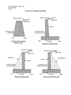
Transcription of Weld Connections - Texas A&M University
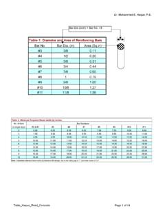
1 weld Connections Shear Plane Throat = w x Cos 450. = w w Root w FILLET weld . Electrodes should be selected to match the base metal. Use E70XX electrodes with steels that have a yield stress less than 60 ksi. Use E80XX electrodes with steels that have a yield stress of 60 ksi or 65 ksi. Nominal load capacity of weld , Rn = Fw Aw = [ w L ] Fw Design Strength, Rn = Fw Aw = [ w L ] Fw Where = Where Fw = nominal strength of the weld metal per unit area = FEXX. Fw based on the angle of the load to the longitudinal axis of the weld ( ): Fw = FEXX [ + Sin ]. Dr. Haque, ( weld Connections - Rev) Page 1 of 7. Fillet weld symbols E70. 1/4 7 Near side (arrow side). 1/4 7. E70. Other side 1/4 7. E70. 1/4 7 Both sides E70. 1/4 7 weld all around Field weld E70. 1/4 7. Dr. Haque, ( weld Connections - Rev) Page 2 of 7. EXAMPLE 1: Determine the strength of the following welds. 8 . (a) 3/4 weld , 8 long, loaded along the weld 8.
2 8 . 450. (c) 3/4 weld , 8 long, loaded at a 450 to (b) 3/4 weld , 8 long, loaded perpendicular to the weld the weld (a) Nominal Design Strength, Rn = Fw Aw = [ w L ] Fw Where = Rn = [ (3/4 )(8 )]( ) = kips (b) Fw = FEXX [ + Sin ] = FEXX ( ) { Sin = Sin (900 ) = 1}. Rn = x = kips (c) Fw = FEXX [ + Sin ] = FEXX ( ) { = 450 }. Rn = x = kips Dr. Haque, ( weld Connections - Rev) Page 3 of 7. Example 2: Determine the design strength for C-shaped welds. Use E70XX. electrodes and a 3/16 Fillet weld . PL (A36 Steel). 8 . E70. 3/16 PL (A36 Steel). 10 . For 3/16 weld , 2-10 long, loaded along the weld Rw(L) = (3/16 )(2x10 )]( ) = kips For 3/16 weld , 8 long, loaded perpendicular to the weld Rw(T) = (3/16 )(8 )]( ) = Kips Without considering the weld and load orientation, weld Design Strength AISC Specification, Equation (J2-10a) (AISC Steel Manual 14th Ed.). Rn = + = Kips weld Design Strength considering the added contribution of the transverse welds while reducing the contribution of the longitudinal welds, AISC Specification, Equation (J2-10b) (AISC Steel Manual 14th Ed.)
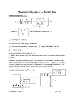
3 Rn = ( ) + ( ) = Kips Select the largest one, Rn = ( )( ) = Kips Dr. Haque, ( weld Connections - Rev) Page 4 of 7. Example 3: Determine the LRFD design strength of the connection as shown in Figure. Follow the following steps: (a) Strength based on yielding in the gross section (b) Strength based on tensile fracture (c) Strength based on block shear failure (d) weld strength. (e) What is the design strength of this connection ? PL (A36 Steel). 8 . E70. 5/16 PL (A36 Steel). 10 . SOLUTION: (a) Strength based on yielding in the gross section t Pn = t Fy Ag = (36 ksi) (8" x ") = Kips (b) Strength based on tensile fracture Ae = U x An t Pn = t Fu Ae AISC Specification TABLE , Case 1, U= 1. Ae = (1) (8" x ") = 4 Sq in. Dr. Haque, ( weld Connections - Rev) Page 5 of 7. t Pn = t Fu Ae = ( ) (58 ksi) (4 sqin) = 174 Kips. (c) Strength based on block shear failure Design Block Shear Strength = Rn where = Rn = Fu Anv + Ubs Fu Ant <= Fy Agv + Ubs Fu Ant Agv = (2 x 10")( ") = 10 sq in Anv = 10 sq in Ant = 8" x " = 4 sq in Ubs = for uniform tension stress Rn = (58 ksi)(10 sq in) + (1)(58 ksi)(4) = 580 kips Rn = (36 ksi)(10 sq in) + (1)(58 ksi)(4) = 448 Kips CONTROLS.
4 Rn = 448 = 336 kips (d) weld strength. For 5/16 weld , 2-10 long, loaded along the weld Rw(L) = (5/16 )(2x10 )]( ) = kips For 5/16 weld , 8 long, loaded perpendicular to the weld Rw(T) = (5/16 )(8 )]( ) = Kips AISC Specification (AISC Steel Manual 14th Ed.). Equation (J2-10a): Rn = + = Kips Equation (J2-10b): Rn = ( ) + ( ) = Kips Design Wed strength, Rn = ( )( ) = Kips (e) What is the design strength of this connection ? Based on (a), (b), (c), and (d), Yielding controls (a): The design Strength = Kips. Dr. Haque, ( weld Connections - Rev) Page 6 of 7. Backing bar Butt Groove weld Tee Groove weld Corner Groove weld Fig 1: Complete penetration groove welds Fig 2: Partial penetration groove welds Dr. Haque, ( weld Connections - Rev) Page 7 of 7.