Transcription of WESTCODE
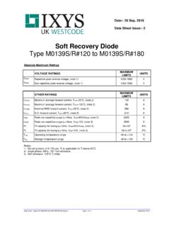
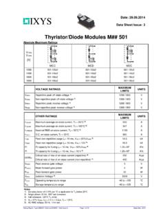
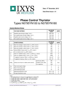
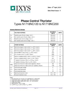
1 Data Sheet. Types W0642WC160 to W0642WC240 Issue 1 Page 1 of 9 September, 2004 WESTCODEAn ixys CompanyDate:- 20 Sep 2004 Data Sheet Issue:- 1 Rectifier DiodeTypes W0642WC160 to W0642WC240 Old Type No.: SW16-24 CXC380 Absolute Maximum RatingsVOLTAGE RATINGSMAXIMUMLIMITSUNITSVRRMR epetitive peak reverse voltage, (note 1)1600-2400 VVRSMNon-repetitive peak reverse voltage, (note 1)1700-2500 VOTHER RATINGSMAXIMUMLIMITSUNITSIF(AV)MMaximum average forward current, Tsink=55 C, (note 2)642 AIF(AV)MMaximum average forward current. Tsink=100 C, (note 2)477 AIF(AV)MMaximum average forward current.
2 Tsink=100 C, (note 3)291 AIF(RMS)MNominal RMS forward current, Tsink=25 C, (note 2)1157 AIF( ) forward current, Tsink=25 C, (note 4)997 AIFSMPeak non-repetitive surge tp=10ms, Vrm=60%VRRM, (note 5)5500 AIFSM2 Peak non-repetitive surge tp=10ms, Vrm 10V, (note 5)6050AI2tI2t capacity for fusing tp=10ms, Vrm=60%VRRM, (note 5)151 103A2sI2tI2t capacity for fusing tp=10ms, Vrm 10V, (note 5)183 103A2sTj opOperating temperature range-40 to +180 CTstgStorage temperature range-40 to +200 CNotes:-1) De-rating factor of per C is applicable for Tj below 25 ) Double side cooled, single phase; 50Hz, 180 ) Single side cooled, single phase; 50Hz, 180 ) Double side ) Half-sinewave, 180 C Tj An ixys Company Rectifier Diode Types W0642WC160 to W0642WC240 Data Sheet.
3 Types W0642WC160 to W0642WC240 Issue 1 Page 2 of 9 September, TEST CONDITIONS (Note 1)UNITSVFMM aximum peak forward peak forward IRRMPeak reverse current--15 Rated VRRMmAIRRMPeak reverse current--15 Rated VRRM, Tj=25 CmAQrrRecovered charge-1000- CQraRecovered charge, 50% Chord-525750 CIrrReverse recovery current-70-AtrrReverse recovery time-15-ITM=500A, tp=500 s, di/dt=10A/ s, Vr=50V side cooledK/WRthJKThermal resistance, junction to side cooledK/WFMounting :-1) Unless otherwise indicated Tj=180 An ixys Company Rectifier Diode Types W0642WC160 to W0642WC240 Data Sheet.
4 Types W0642WC160 to W0642WC240 Issue 1 Page 3 of 9 September, 2004 Notes on Ratings and Voltage Grade TableVoltage GradeVDRM VDSM VRRMVVRSMVVD VRDC Extension of Voltage GradesThis report is applicable to other voltage grades when supply has been agreed by De-rating FactorA blocking voltage de-rating factor of C is applicable to this device for Tj below 25 Snubber ComponentsWhen selecting snubber components, care must be taken not to use excessively large values of snubbercapacitor or excessively small values of snubber resistor. Such excessive component values may lead todevice damage due to the large resultant values of snubber discharge current.
5 If required, please consultthe factory for Computer Modelling Device Dissipation CalculationsTAVTTTAVrffWrffVVI ++ =2220024and:KjthAVTTTRTW = =maxWhere VT0= , rT= ,Rth = Supplementary thermal impedance, see table below andff = Form factor, see table Thermal ImpedanceConduction Angle6 Phase (60 )3 Phase (120 ) Wave (180 ) wave Double Side wave Single Side wave Double Side wave Single Side FactorsConduction Angle6 Phase (60 )3 Phase (120 ) Wave (180 ) An ixys Company Rectifier Diode Types W0642WC160 to W0642WC240 Data Sheet. Types W0642WC160 to W0642WC240 Issue 1 Page 4 of 9 September, Calculating VF using ABCD CoefficientsThe on-state characteristic IF vs.
6 VF, on page 6 is represented in two ways;(i) the well established VT0 and rT tangent used for rating purposes and(ii) a set of constants A, B, C, D, forming the coefficients of the representative equation for VF interms of IF given below:()FFFFIDICIBAV + + +=lnThe constants, derived by curve fitting software, are given below for both hot and cold characteristics. Theresulting values for VF agree with the true device characteristic over a current range, which is limited tothat C Coefficients180 C An ixys Company Rectifier Diode Types W0642WC160 to W0642WC240 Data Sheet.
7 Types W0642WC160 to W0642WC240 Issue 1 Page 5 of 9 September, Thermal Impedance Calculation == =npptptperr11 Where p = 1 to n, n is the number of terms in the series and:t = Duration of heating pulse in Thermal resistance at time Amplitude of pth term. p= Time Constant of rth coefficients for this device are shown in the tables Single Side 10-3 Double Side 10-3 Reverse recovery ratings(i) Qra is based on 50% Irm chord as shown in Fig. 1 Fig. 1(ii) Qrr is based on a 150 s integration time =srrrrdtiQ 1500.(iii)21 ttFactorK=WESTCODEWESTCODEWESTCODEWESTCO DE An ixys Company Rectifier Diode Types W0642WC160 to W0642WC240 Data Sheet.
8 Types W0642WC160 to W0642WC240 Issue 1 Page 6 of 9 September, 2004 CurvesFigure 1 - Forward characteristics of Limit deviceFigure 2 - Transient thermal impedance1001000100000123456 Maximum instantaneous forward voltage - VFM (V)Instantaneous forward current - IFM (A)180 C25 (s)Thermal impedance (K/W)SSC 3 - Maximum surge Rating100010000100000 Total peak half sine surge current - IFSM (A) + + +07 Maximum I2t (A2s)13510151050 100 Duration of surge (ms)Duration of surge (cycles @ 50Hz)I2t: VRRM 10 VTj (initial) = 180 CIFSM: VRRM 10 VIFSM: VR=60% VRRMI2t: VR=60% VRRMW0642WC160-240 Issue 1W0642WC160-240 Issue 1W0642WC160-240 Issue 1 WESTCODEWESTCODEWESTCODEWESTCODE An ixys Company Rectifier Diode Types W0642WC160 to W0642WC240 Data Sheet.
9 Types W0642WC160 to W0642WC240 Issue 1 Page 7 of 9 September, 2004 Figure 4 - Total recovered charge, QrrFigure 5 - Recovered charge, Qra (50% chord)1001000100001101001000 Commutation rate - di/dt (A/ s)Total recovered charge - Qrr ( C)Tj = 180 C1500A1000A500A250A100100010000110100100 0 Commutation rate - di/dt (A/ s)Recovered charge - Qra ( C)Tj = 180 C1500A1000A500A250 AFigure 6 - Peak reverse recovery current, IrmFigure 7 - Maximum recovery time, trr (50% chord)1010010001101001000 Commutation rate - di/dt (A/ s)Reverse recovery current - Irm (A)1500A1000A500A250 ATj = 180 C1101001101001000 Commutation rate - di/dt (A/ s)Recovery time - trr ( s)Tj = 180 C1500A1000A500A250AW0642WC160-240 Issue 1W0642WC160-240 Issue 1W0642WC160-240 Issue 1W0642WC160-240 Issue 1 WESTCODEWESTCODEWESTCODEWESTCODE An ixys Company Rectifier Diode Types W0642WC160 to W0642WC240 Data Sheet.
10 Types W0642WC160 to W0642WC240 Issue 1 Page 8 of 9 September, 2004 Figure 8 Forward current vs. Power dissipation Double Side CooledFigure 9 Forward current vs. Heatsinktemperature - Double Side Cooled0200400600800100012001400160018000 20040060080010001200 Mean Forward Current (A) (Whole cycle averaged)Maximum Forward Dissipation (W)6 3 Forward Current (A) (Whole cycle averaged)Maximum permissable heatsink temperature ( C)6 3 10 Forward current vs. Power dissipation Single Side CooledFigure 11 Forward current vs. Heatsinktemperature Single Side Cooled0100200300400500600700800900010020 0300400500600700 Mean Forward Current (A) (Whole cycle averaged)Maximum Forward Dissipation (W)6 3 forward current (A) (Whole cycle averaged)Maximum permissible heatsink temperature ( C)6 3 1W0642WC160-240 Issue 1W0642WC160-240 Issue 1W0642WC160-240 Issue 1 WESTCODEWESTCODEWESTCODEWESTCODE An ixys Company Rectifier Diode Types W0642WC160 to W0642WC240 Data Sheet.