Transcription of Why 50% of Products Fail EMC Testing the First Time
1 Why 50% of Products fail EMC Testing the First Time intertek Testing Services NA, Inc. 70 Codman Hill Road, Boxborough, MA 01719. Phone: 800-967-5352 Fax: 978-264-9403. Email: Web: Summary A large percentage of electronic Products fail to meet their target EMC requirements the First time they are tested. In this article we look at some of the possible reasons for that failure rate, and what designers and manufacturers can do to improve the success rate and therefore time to market. Why do 50% fail ? During the last several years, we have observed that initial EMC test failure rates for electronic Products have decreased gradually. Improved success may be the result of growing awareness of EMC design considerations, use of EMC software, reduced circuit dimensions or all of these factors.
2 Nevertheless, we continue to see EMC test failure rates around 50%. Looking more deeply into the numbers, we note that, for example, medical Products are slightly more successful (~40% initial failure) at meeting their EMC objectives than information technology equipment (ITE). One might expect otherwise from the added performance constraints of the medical EMC standard IEC 60601-1-2 over the ITE standards CISPR 22 and 24, but two factors may work in favor of medical Products . They are often designed more conservatively and with more review than ITE, and the IEC 60601- 1-2 standard it self allows justified derogations from the limits. But overall, the same basic EMC. considerations apply to both medical and ITE.
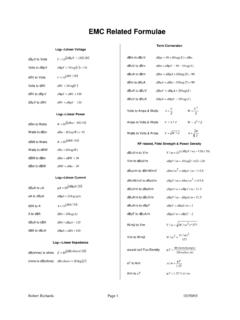
3 60 Fortunately, the EMC learning curve for Products that fail 50 ITE. initially is quite steep. Presumably taking advantage of both the EMC education provided by the First go-around, as well 40. Medical as the pinpointing of EMC problems, manufacturers reduce 30 the failure rate on the EMC re- Testing to the level of 5% - Learning curve 7%. Very challenging Products may require a third round of Failure 20 plus knowing exactly what EMC Testing , for which we observe a failure rate reduced to 10 1% - 2%. 1st 2nd 3rd trial Based on our experiences with a wide variety of equipment suppliers, we can summarize the leading observed causes of initial EMC failure as: Lack of knowledge of EMC principles Failure to apply EMC principles Application of incorrect EMC regulations Unpredicted interactions among circuit elements Incorporation of non-compliant modules or subassemblies into the final product These topics are discussed briefly in the context of a product design and development program intended to maximize the likelihood of success in the initial EMC Testing .
4 1. EMC regulations Although RF interference considerations have existed since the advent of radio, commercial EMC. regulations (both emissions and immunity) are relatively recent and continuously changing. Equipment designers and regulatory compliance engineers have to work hard to identify and keep abreast of the EMC. regulations that impact their Products . Of course, regulations should not be the only design driver. In the USA, the Communications Act of 1934 established the framework for resolving radio interference issues. Parallel laws were enacted around the world, with Germany providing early leadership in laws and standards that provided a model for the European Union. After the Second World War and the growth of electronics, specialized EMC standards were created to assure reliable equipment operation in such critical applications as aircraft, military, medical and automotive.
5 The regulation of RF emissions from consumer Products was given a boost from the advent of the personal computer. Numerous complaints of interference to radio and TV reception from personal computers led in the United States to the adoption of Subpart J to the FCC's Part 15 rules in 1979. The regulation of RF emissions from personal computers has spread throughout the world, with a few examples shown below: FCC Part 15, subpart J 1979. IEC CISPR 22 1985. VCCI in Japan 1985. Canada Radio Act 1988. Australian EMC Framework 1996. Taiwan ITE EMI 1997. Korea ITE EMC 1998. Singapore EMI for telecom 2000. In 1989 the FCC consolidated its Part 15 rules into Subparts A, B and C. But thanks to the unstoppable flow of new communication technologies, the Part 15 rules have grown back to include Subpart G, with a new Subpart H already proposed.
6 Today, RF emissions are regulated in most developed countries to protect broadcast services (radio, TV) and sensitive services (radio-navigation, satellite communications, radio- astronomy). The First widespread application of RF immunity requirements was introduced with the European Union's EMC Directive published in 1989 and originally to take effect in 1992. However, the lack of suitable EMC. standards and the lagging preparedness of manufacturers led to a delay until 1996. The original EMC. Directive 89/336/EEC is replaced by a new Directive 2004/108/EC, with a transition period 20 July 2007 . 20 July 2009. EMC for radio equipment in the EU is mandated by the R&TTE (Radio and Telecommunications Terminal Equipment) Directive 1999/5/EC.
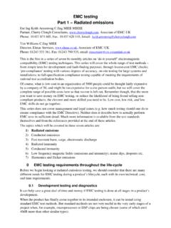
7 Worldwide EMC regulations, including limits and measurement procedures, are changing constantly and represent a moving target for product development. 2. RF emissions limits have been established for the threshold sensitivities of typical victim receivers such as radio and TV, and on the protection distances that may be available to increase the spacing between RF. emitter and victim. The common protection distances are 10 meters for residential environments and 30. meters for non-residential. Most emissions standards allow scaling to other measurement distances such as 3 meters. The equipment designer needs to know that the EMC environment interpretation of EMC environments can differ USA EU+. between jurisdictions.
8 In the USA, the FCC has defined the Part 15 Class A environment as anything except residential or consumer. EU non-residential industrial Class A. generic EMC regulations define Class B more broadly. It may include commercial and light residential, industrial environments. For ITE, however, it is Class B residential commercial, acceptable to allow Class A emissions in light industrial commercial and light industrial locations. Emissions increase Immunity disturbances Immunity environments are generally defined by the electromagnetic threats or disturbances that may exist there. For example, the generic industrial immunity standard IEC 61000-6-2 defines an industrial environment both from the nature of the AC connection: - to a power network supplied from a high or medium voltage transformer dedicated to the supply of an installation feeding manufacturing or similar plant which could conduct disturbances from the equipment to other victims, and to the surrounding threats as.
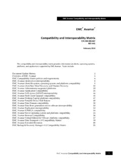
9 - industrial, scientific and medical (ISM) apparatus - heavy inductive or capacitive loads are frequently switched - currents and associated magnetic fields are high The equipment designer or design team needs to assure that their EMC objectives take into account any regulatory differences among jurisdictions regarding the definitions of the EMC environment. Consider EMC early in the design process There are many opportunities during the product development process between concept and market entry where EMC criteria should be established, The design process validated, tested and perhaps modified. The Design concept Target System feedback implied in Figure 3 does not necessarily rules mean a mid-course correction (although one might be justified), but rather an opportunity to capture EMC information for use in future projects as a means of process improvement.
10 ISO 9000- registered manufacturers should consider including Regulatory Functional Initial release evaluation design 3. these review steps in their equipment development program. Some specific EMC considerations are suggested below for each of the design steps shown in Figure 3: Target Specifications The details (include functional and regulatory . EMC). Are all the jurisdications specified? Have the requirements changed? Is the environment correct? System Architecture The structure and details EMC. How many layers in PCBs? Are reactive circuits located away from I/O ports? Are I/O ports isolated/shielded? Are IC families appropriate for speeds needed? Will housing provide shielding? Design Rules The circuit and layout constraints EMC.