Transcription of Wide Voltage Conventional Detectors - Apollo Fire
1 SERIES 65 ENGINEERING PRODUCT Voltage Conventional DetectorsInformation in this guide is given in good faith, but Apollo Fire Detectors Limited cannot be held responsible for any omissions or errors. The company reserves the right to change specifications of products at any time without prior 65 incorporates well-proven sensing technologies, including an Integrated Circuit based on that used in XP95 analogue addressable Series 65 range has a wide operating Voltage of 9 33V and consists of ionisation, integrating ionisation and optical smoke Detectors , four grades of heat detector and a range of product guide aims to provide engineers with comprehensive information on Series 65, in order to be able to design optimum solutions to fire protection Fire Detectors is a Halma company and operates from one site at Havant, near Portsmouth, England.
2 All departments Research and Development, Sales and Marketing, Manufacturing and Finance are located here. Apollo applies the most modern production techniques and has invested in sophisticated manufacturing equipment to ensure consistent high quality of product and fast response to customer requirements. Through planned expansion Apollo has reached a leading position in the market for professional fire Detectors and exports over half of its production to countries around the Fire Detectors is certified to ISO9001:2000 by the Loss Prevention Certification 3 SERIES 65 TABLE OF CONTENTSI onisation Smoke Detector Operating principles 4 Integrating version 5 Options 5 Safety note 5 Environmental characteristics 5 Technical data 6 Optical Smoke Detector Operating principles 7 Options 7 Technical data 8 Heat Detector Operating principles 9 Options 9 Response tine 10 Technical data 11 Mounting Bases Mounting Base 12 Relay Base 13 Sav-Wire Base 14 Sounder Base 15 MiniDisc Remote Indicator Specification 17 Interchangeability 18 Control Panel Compatibility 18 EMC 18 Approvals and Regulatory Compliance 18page 4 Apollo Fire Detectors Limited 1991/RFSERIES 65 IONISATION SMOKE Detectors eries 65 Standard Ionisation Smoke Detector s Part nosIonisation detector 55000-217 Detector with flashing LED 55000-216 Detector with magnetic test switch &
3 Flashing LED 55000-215 Series 65 Integrating Ionisation Smoke Detector Ionisation detector 55000-220 Detector with flashing LED 55000-219 Detector with magnetic test switch & flashing LED 55000-218 OPERATINGPRINCIPLESThe detector has a moulded self-extinguishing white polycarbonate case with wind resistant smoke inlets. Nickel plated stainless steel wiper contacts connect the detector to the the detector case a printed circuit board has the ionisation chamber mounted on one side and the signal processing electronics on the Side view, Series 65 Ionisation Smoke DetectorThe ionisation chamber consists of a reference chamber contained inside a smoke chamber (Fig. 1). The outer smoke chamber has inlet apertures fitted with insect resistant mesh. The radioactive source holder and smoke chamber form positive and negative electrodes respectively.
4 An Americium 241 radioactive source mounted within the reference chamber irradiates the air in both chambers, producing positive and negative ions. A Voltage across the electrodes produces an electric are attracted to the electrode of the opposite sign to their own charge. Many recombine but a small electric current flows between the electrodes. At the junction between reference and smoke chambers the sensing electrode converts variations in chamber current into Voltage smoke particles enter the ionisation chamber ions become attached to them with the result that the current flowing through the chambers decreases. This effect is greater in the smoke chamber than in the reference chamber, and the imbalance causes the sensing electrode to become more Voltage at the sensing electrode is fed to a comparator where it is compared with a factory-set clean air reference Voltage .
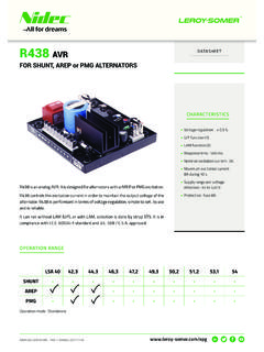
5 If the monitored Voltage exceeds the reference Voltage , the comparator switches the alarm latch on, increasing the current drawn from the supply from about 40 A to a maximum of 75mA. This fall in the impedance of the detector is recognised by the control panel as an alarm alarm latch current also illuminates the detector integral LED. A remote indicator connected between the L1 IN terminal and the R terminal will have a Voltage equal to the supply Voltage less 1 volt across it and so will illuminate. See page 17 for details of the remote ensure correct operation of the detector the control panel must be arranged to supply a maximum of 33 volts DC and a minimum of 9 volts DC in normal supply may fall to 6 volts DC in alarm conditions if a supply current of at least 10mA is available at this Voltage . To ensure effective illumination of the integral LED and any remote indicator, the supply to the detector should exceed 12 restore the detector to quiescent condition, it is necessary to expel any smoke and interrupt the electrical supply to the detector for a minimum of one 5 requirements specified in the Recommendations for ionisation smoke Detectors in implemetation of radiation standards published by the Nuclear Energy Agency of the Organisation for Economic Co-operation and Development (OECD) is no limit to the number of ionisation smoke Detectors which may be installed in any fire protection system within the United Kingdom.
6 See Certificate of Approval no. TA1 issued by the Health & Safety Executive for further regulations depend on local standards and legislation, but, in the UK, the number of ionisation smoke Detectors in any building or premises shall be less than 500. See Certificate of Approval no. TA3 of 1999 issued by the Health & Safety Executive for further the end of their recommended working life of ten years, ionisation smoke Detectors should be returned to Apollo for safe disposal or disposed of in an otherwise locally approved and environmentally safe manner. Please see A guide to the care, maintenance and servicing of Apollo products , on storage and handling can be given by Apollo Fire Detectors and full details can be requested from:Radioactive Substances Regulation FunctionEnvironment AgencyRio HouseWaterside DriveAztec West, AlmondsburyBristol BS32 4 UDOutside the UK, please contact the relevant national CHARACTERISTICSS eries 65 ionisation smoke Detectors operate over a temperature range of 20 C to +60 Detectors have some sensitivity to air movement (wind).
7 The extent to which the sensor output will change depends on the wind speed and on the orientation of the detector relative to the wind direction. Relatively small changes in wind direction can cause significant changes in sensor wind speeds up to 1m/s (200ft/min) sensitivity will change by less than 20%. Continuous operation in wind speeds greater than 2m/s (400ft/min) is not recommended. However, wind speeds up to 10m/s (2000ft/min) can be tolerated for short periods and will not under any conditions increase the probability of false 65 ionisation smoke Detectors are supplied in individual packing with a red lid serving as a dust cover which can be left in place after fitting to prevent ingress of foreign material until commissioning of the system takes place. At this point the covers must be in the Integrating Ionisation Smoke Detector protects against transient levels of smoke above the normal threshold level for 10 to 20 seconds.
8 The sensitivity of the detector is not affected by this (Apply to standard and integrating versions)1. Flashing LED: The alarm indicating LED flashes when the detector is in a quiescent Magnetic test switch and Flashing LED: A magnetic test switch in the circuit of the detector can be magnetically activated from outside the case to initiate an alarm condition for test and commissioning purposes. A flashing LED, as outlined above, is also NOTEIn the United Kingdom, ionisation smoke Detectors are subject to the requirements of the Radioactive Substances Act 1993 and to the Ionising Radiations Regulations 1999 made under the provisions of the Health and Safety at Work Act Detectors , independently tested by the National Radiological Protection Board (NRPB), conform to all the page 6technical dataSupply Voltage :9 to 33V DCRipple Voltage :2V peak to peak maximum at to 100kHzQuiescent Current:20 45 A at 24 VSwitch-on Surge Current:110 A Alarm Voltage :6 to 33 VNormal Alarm Current:61mA at 28V 52mA at 24V 18mA at 10 VAlarm Indicator:Red, Light Emitting Diode (LED)Design Alarm Load:420O in series with a 2V dropHolding Voltage :6V (min)Holding Current:10mA (min)Minimum Voltage Requiredto Illuminate Indicator.
9 12 VAlarm Reset Voltage :1 VAlarm Reset Time:1 secondRemote OutputCharacteristics:Remote is a current sink to the negative line limited to 17mACalibration:Factory set to AV of :Nominal threshold Y value of to EN 54 7: 2000 Temperature Range:Maximum continuous operating temperature 60 CMinimum continuous operating temperature 0 CMinimum operating temperature 20 C(no condensation or icing)Storage 30 C to +80 CTemperature Compensation:Automatic compensation by dual chambers to comply with EN 54 7: 2000 across the operating temperature rangeHumidity:0% to 95% relative humidity (no condensation)Atmospheric Pressure:Automatic compensation by dual chambers to maintain sensitivity up to a height of 2000mWind Speed:10m/s maximumIP Rating:23D in accordance with BS EN 60529 EMC, approvals andregulatory compliance:Refer to Page 18 of this documentDimensions: (dia.)
10 X height)Detector: 100x42mmDetector in Base: 100x50mmWeights:Detector: 102gDetector in Base: 153gMaterials:Detector housing: White polycarbonate rated V-0 in accordance with UL : Nickel plated stainless steelCE 0832 TECHNICAL DATAS pecifications are typical and given at 23 C and 50% relative humidity unless specified Type:Point type smoke detector for fire detection and alarm systems for buildingsDetection Principle:Ionisation chamberChamber Configuration:Twin compensating chambers using one single-sided ionising radiation sourceRadioactive Isotope:Americium 241 k Bq, CiSupply Wiring:Two wire monitored supply, polarity insensitiveTerminal Functions:L1 IN and L2: supply in connections (polarity insensitive)L1 OUT and L2: supply out connections (polarity insensitive). R: remote indicator negative connectionpage 7 SERIES 65 OPTICAL SMOKE DETECTORO ptical Smoke Detector s Part nosStandard detector 55000-317 Detector with flashing LED 55000-316 Detector with magnetic test switch & flashing LED 55000-315 OPERATINGPRINCIPLESThe Series 65 Optical Smoke Detector has a moulded self-extinguishing white polycarbonate case with wind resistant smoke inlets.