Transcription of Wind Farm Electrical Systems.pptx [Read-Only]
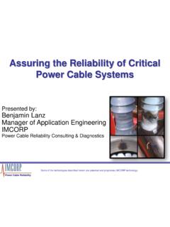
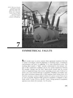
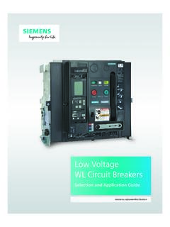
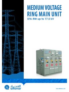
1 Wind Farm Electrical Systems History of Wind Power Pitstone Windmill, believed to be the oldest windmill in the British Isles The Giant Brush Windmill in Cleveland, Ohio During the winter of 1887 88 Brush built what is today believed to be the first automatically operating wind turbine for electricity generation. It was a giant the World's largest with a rotor diameter of 17 m (50 ft.). and 144 rotor blades made of cedar wood. Note the person mowing the lawn to the right of the wind turbine. The turbine ran for 20 years and charged the batteries in the cellar of his mansion. Despite the size of the turbine, the generator was only a 12 kW model. Grandpa's Knob The first large scale electricity producing windmill (the world's largest at the time) was installed in 1941 at Grandpa's Knob, on the border of Castleton and West Rutland, VT, to take advantage of New England's strong wind energy regime. The turbine restarted on March 3, 1945 and operated normally until March 26, when the turbine suffered a massive failure.
2 One of the 75 foot blades suddenly snapped off and hurled 700 feet down the mountain. The experiment, still largely considered a success, ended with the turbine being razed in the summer of 1946. Wind Turbine Generator Introduction A small anemometer and wind vane on top of the wind turbine electronically tell a controller which way to point the rotor into the wind. Then the "yaw drive" mechanism turns gears to point the rotor into the wind. Nacelle Design 1. Maintenance Hoist. Nacelle Details 2. Generator: 800 kW, Induction, 4 poles, 690 Volts. 3. Cooling system (Air). 4. Top Control unit. (PLC). 5. Gear box: ratio 6. main shaft 7. Maintenance Rotor Lock System. 8. Blade. 9. Blade Hub 10. Nose cone 11. Blade bearing (for pitch control). 12. Base Frame 13. Hydraulic Unit (disk brakes, gear box ). 14. Gear frame attachment 15. Yaw Ring 16. Brake 17. Tower (three sections). 18. Yaw motor drive: kW. 19. Cardan 20. Windvane for yaw control. 21. Anemometer for pitch control. Nacelle Details Induction (Asynchronous) Machine Induction Machine Reactive Power Wind Turbine Induction Generator Induction Generator Issues Capacitors require to provide excitation Fixed speed operation only Gearbox torque is of concern Can't provide reactive or voltage control Uncompensated wind farm is a consumer of reactive power (see chart).
3 Reactive power compensation is needed to control the voltage Wound Rotor Induction Machine Wound Rotor Induction Generator Singly Fed Induction Generator Doubly Fed Induction Generator Converter Rotor Energy Dissipated Absorbs Over speed Rotor Energy & Provides Output Energy Doubly Fed Induction Generator Converter Absorbs Energy for Under speed Rotor & Provides Output Energy Wind Turbine Generator Constant Speed Systems Squirrel Cage Induction Generator Cheap & Simple Torque variations not compensated Flicker Capacitors to compensate reactive power Wind Turbine Generator Variable Speed Systems Doubly Fed (Wound Rotor) Induction Generator DFIG. Optimum power control Converter size Restricted speed variability Expensive Wind Turbine Generator Variable Speed Systems Squirrel Cage Induction Generator Optimum power control 100% speed variability Converter size Expensive Wind Turbine Generator Variable Speed Systems Permanent Magnet Synchronous Generator Optimum power control 100% speed variability Without Gearbox Converter size Generator complexity Very expensive WT Generator Comparison Wind Farms A wind farm is a collection of wind turbines in the same location.
4 Wind turbines are often grouped together in wind farms because this is the most economical way to create electricity from the wind. If multiple wind turbines are placed too close to one another, the efficiency of the turbines will be reduced. Each wind turbine extracts some energy from the wind, so directly downwind of a turbine winds will be slower and more turbulent. For this reason, wind turbines in a wind farm are typically placed 3 5 rotor diameters apart perpendicular to the prevailing wind and 5 10 rotor diameters apart parallel to the prevailing wind. Energy loss due to the "Wind Park Effect" may be 2 5%. The largest wind farm in the world is in Texas. It has 421 wind turbines spread out over 47,000 acres. This wind farm can produce a total of Megawatts of electricity. Wind Farm Layout to minimize "Wind Park Effect". Comparison Wind Farm & Conventional Power Plant Wind Farm Conventional Power Plant Configuration Multiple small generators One large generator Location Determinate on wind Sited for economics speed (transmission access).
5 Control 1st Generation had no Voltage & Frequency voltage ride through Reactive Power Capacitor banks and Self generated power electronics Reliability Output varies with wind Output predictable Generator Reactive Capability Induction generators no inherent Lagging reactive production capability MVar MW. Leading Lagging Doubly fed induction generators pf +.95. +/ pf MVar MW. Leading .95p f Synchronous Generator reactive Lagging capability MVar MW. Leading First Generation Wind Turbines Small Output (less than 1 MW). Fixed Speed Induction Generator Required Capacitive Compensation To Operate No Low Voltage Ride Through (LVRT); Tripped Off For Low System Voltage No Reactive Power Support No SCADA Control/Data to System Operator Low Penetration Level In Grid August 2003 Blackout Higher System Penetration (5 10%). No LVRT/Reactive Support Aggravated Situation FERC Order No. 661 A, Interconnection for Wind Energy (NERC Member Grid Codes Also). Three Common Components To Grid Codes: 1. LVRT Requirements 2.
6 Reactive Power; Provide +/ PF and Dynamic Reactive Support If Required 3. Provide Data to Transmission Operator (SCADA). Low Voltage Ride Through FERC 661A. First Generation WTG No LVRT. 1. Fault on utility transmission grid 2. Transmission system voltage drops rapidly. 5. Voltage returns to normal. But, no generation remains on line. 3. Wind generation 4. Fault clears trips off line because in 600 mS. voltage is below pu at generator terminals for 5 cycles. WTG with SVC (or enhanced DFIG). 1. Fault on utility transmission grid 2. Transmission system voltage drops rapidly. 3. SVC detects low voltage and injects reactive energy to quickly rebuild voltage at the wind generator above pu threshold Reactive Power Compensation Shunt capacitors, switched in blocks, relatively inexpensive, not good for transient events Switching block of capacitance can swing the voltage up or down and this variation is felt as an abrupt change in torque on the turbine gearboxes Static var Compensators Provide Continuously Adjustable Dynamic +/ PF Control, Very Expensive SVC Configuration Compensation Cap Bank vs SVC.
7 Static Var Compensator with Cap Banks Switched Capacitor Banks Typical Uncompensated Wind Farm Losses 100 MW 230 kV. 60/100 MVA. 9% Z. 600V To Utility 100 MW. Transmission 18 MVAR Grid kV. Power 100% PF Transformer Losses GSU Collector Grid Losses Losses Collector Grid Turbines Charging MVAR MVAR MVAR. 0 MVAR 9 MVAR Inductive MVARs Capacitive MVARs 18 MVAR. Losses Reactive Power Budget Mendota Hills Reactive Power Calculation 18. 16 Generator 99% pf lagging 14. Xformer I2X loss 12. 10 line I2X. 50 MW Wind Turbine Generation 8 loss(estimate)). MVAR. PF UDG line charging 6. 4 Xformer I2X loss 2. 2 Total 0. Compensation(leading). -2. -4. Transformer 138 kV kV MVAR Losses 63 GSU Transformers kV kV MVAR Losses 20 miles of kV XLPE 133% Insulated cable Wind Farm SCADA. Provides Integrated Control & Data for Each WTG & Wind Farm System Voltage & PF. Larger Wind Farm System (Units > 1MW). Utility (115 kV). Tie Breaker Line Transformer Switchgear or Open Substation G G G G G. G G G G G. G G G G G.
8 G G G G G Windfarm Substation ( kV). G G G G G. Collector Feeder Breakers Collector Bus Wind Farm Transformer Winding Configuration WTG. Utility Tie Transformer Primary Grounded Wye, WTG GSU Delta Primary, Grounded Secondary Grounded Wye, Tertiary Delta; sometimes Wye Secondary & Tertiary Primary Grounded Wye, Secondary Delta WTG GSU. Collector System One Line (Partial). Collector System Site Plan Wind Farm Grounding Cu 4/0 bare conductors SUBSTATION. WIND TURBINES GROUNDING. Cu 500 kcmil Conductors (grid with 3 grounding rings, the 18 inches underground external two are underground). The grounding grids of all the are connected with the substation grid through bare copper conductors, making the whole to be a equipotential space, such a big amount of grounding conductors embedded in the ground produces a very low grounding resistance < 0,5 (typical). Collector System Cabling Collector system cable design considerations include the conductor size (based on system ampacity requirements) and the insulation type and level.
9 The two common insulation types are tree retardant, cross linked polyethylene (TRXLPE) and ethylene propylene rubber (EPR). The insulation level (100%,133% or 173%) depends on the system grounding as well as the magnitude and duration of temporary phase to ground overvoltages under fault conditions. Cable ampacities, and therefore the conductor size, are directly related to five major factors: number of circuits, cable installation geometry and method, thermal resistivity and temperature, cable shield voltages and bonding method and load factor. Cable Sheath Grounding Multi bonded Shield Single bonded Shield Cross bonded Shield Shields transposed at each junction Cable Sheath Grounding Application Multiple grounded sheath systems have lower ampacities due to heating from sheath currents Single grounded sheath systems may have excessive sheath voltage Cross bonded systems require cross bonding at about 7000' foot intervals Wind Farm Challenges If a feeder circuit breaker opens during operation, then that feeder and the operating WTGs will become isolated and form an ungrounded power system.
10 This condition is especially troublesome if a phase to ground fault develops on the feeder; a scenario that causes the unfaulted phase voltages to rise to line voltage levels. This fault can also result in severe transient overvoltages, which can eventually result in failure of insulation and equipment damage. Breaker Opens G. G. G. One remedy is to design for the ungrounded system. This results in G. increased costs due to the higher voltage ratings, higher BIL, and added G. engineering. Another solution is to install individual grounding transformers on each feeder. This adds to equipment and engineering costs and increases the substation footprint. Another solution is to use transfer trip to open feeder CB after WTG CB's open Temporary Overvoltage for SLG Fault Collector System Relaying Several collector system design aspects influence overcurrent protection, including: long circuit lengths may not allow for easy detection of ground faults, system grounding (grounded versus ungrounded or systems grounded through grounding transformers on each feeder), selective coordination of collector system circuits can be quite challenging, as it is often difficult to distinguish faults on feeders when grounding transformers are used, selective coordination with fuses in downstream pad mounted transformers at WTGs, unfaulted phases can be elevated to phase to phase voltage levels with respect to ground during ground faults, loss of phase during faults with single phase tripping and reclosing on the transmission system or downed conductors WTG may feed faults for several cycles (even though the feeder breaker tripped open) if sympathetic tripping of WTGs is not implemented Collector Feeder Coordination Amps X 10 Bus2 (Nom.)