Transcription of WINEGARD
1 1 RoadTrip Digital satellite Mobile TV Antenna for Two ReceiversRoadTrip SD - Stationary satellite TV AntennaRoadTrip SDi - In-Motion satellite TV AntennaINSTALLATION MANUALW inegard Company 3000 Kirkwood St. Burlington, IA 52601-2000319/754-0600 FAX 319/754-0787 in WINEGARD Company, 2008 2452165 Rev3 8/10 WINEGARD 21. Open box and remove packing Lift dome out of box vertically. Then lift unit out of box vertically. Do not turn box and roll out, or turn upside down to Gray Coax Cable (OEM Model)4 White Coax Cable (OEM Model)4 Power Cable (OEM Model)!
2 Parts Included Tools Needed How to UnpackIf using knife to open carton, BE CAREFUL. Do not cut the dome on the Radome 1 Cable entry plate All required screws, washers, bolts, and nylocks1 base with electronics, dish, dual LNBF, mounting feetLIFT UNIT STRAIGHT UP OUT OF CARTON!UNPACKING THE UNITPARTS INCLUDED: The WINEGARD RoadTrip antenna is designed specifically for use with motorized recreational vehicles. WINEGARD recommends using a qualified installer familiar with RV structures and wiring to ensure proper installation and to prevent damage to the RV or satellite 5/06 USE 2 PEOPLE when removing the unit from the carton.
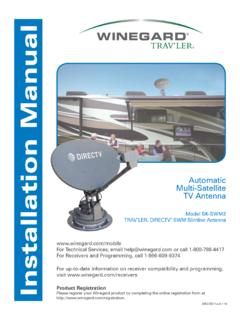
3 !DO NOT PAINT DOME! Painting dome will cause signal degradation and will void your NEEDED FOR UNPACKING & installation :Level Drill w/3/4 bit1-1/4 hole saw (if mounting switch in wall)Phillips screw driver #23/8 Open end wrench 7/16 Open end wrenchSealant (consult RV manufacturer for proper type for your roof material)3 installation DiagramControl UniteLevATIONMOTORLNBFSIDES OF CONTROL UNIT MUST BE PARALLEL TO THE CENTER LINE OF THE VEHICLE AND FACE FRONT OR REAR OF LINE OF THE VEHICLEGPS CABLe(RoadTrip SDi In-Motion models ONLY)GPS ANTeNNA(RoadTrip SDi In-Motion models ONLY)CENTER LINE OF THE VEHICLERev.
4 5/064 Quick Reference GuideYour WINEGARD RoadTrip satellite Tv antenna has been designed to be the most user-friendly Mobile satellite Antenna on the market today. Upon installation of the antenna, or after changing satellite service provider, simply set the switches inside of the dome to the settings shown in the Operation manual. These switches enable the dish to locate the proper satellite for your service provider. They also allow the RoadTrip SDi (in-motion) antenna, to be set for the proper installation option. Simply set the switch, and you re done! Your WINEGARD RoadTrip antenna will locate the proper satellite with just the flip of a InstructionsIt is essential to mount your RoadTrip antenna in the proper position and orientation on your Rv roof to ensure proper operation.
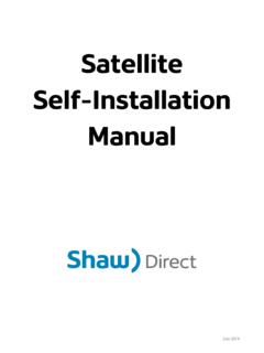
5 Choose a location on your roof clear of obstruction and close to your receiver and power ensure proper tracking with your RoadTrip SDi (in-motion) antenna, you must mount the unit so that the unit is centered on the centerline and cables exit either towards the front or back of the Rv. See Figure 1c OPTION ACABLE EXIT REAR ALIGN FEET EXACTLY SQUARE ON CENTER LINE OF VEHICLE AS SHOWNMV-3500 BACK OF VEHICLEFRONT OF VEHICLEROADTRIPCABLE EXIT FRONT MV-3500 BACK OF VEHICLEFRONT OF VEHICLEFIGURe 1 CMOUNTING OPTION BROADTRIPS witch SettingsAfter mounting the RoadTrip System to your rooftop, you must set the RoadTrip s switch settings for the mounting option chosen and for the satellite television service provider.
6 The chart below lists switch settings for both the RoadTrip SD and RoadTrip SDi. See page 3 of the Operation Manual for detailed instructions. RoadTrip SD (Stationary) (#1 represents Switch DOWN; #0 represents Switch up)SWITCH SeTTINGS OPTIONS0= UP 1= DOWN(#1 represents Switch DOWN; #0 represents Switch up)SWITCH SeTTINGS OPTIONS0= UP 1= DOWNALIGN FEET EXACTLY SQUARE ON CENTER LINE OF VEHICLE AS SHOWN FACTORY PRESET FOR DIRECTV SHOWN Rev. 5/061 2 3 4 5 6 7 81 = DOWN0 = UP0 0 0 0 0 0 0 1 RoadTrip SDi (In-Motion)1 2 3 4 5 6 7 81 = DOWN0 = UP0 0 0 0 0 0 0 1 FACTORY PRESET FOR DIRECTV SHOWNSat.
7 Rcvr. Mt. Option Switch Set Position 1 2 3 4 5 6 7 8 DIRECTV A 0 0 0 0 0 0 0 1 (FACTORY PRESET)DISH NETWORK A 0 0 0 1 0 0 1 1 Sat. Rcvr. Mt. Option Switch Set Position 1 2 3 4 5 6 7 8 DIRECTV A 0 0 0 0 0 0 0 1 (FACTORY PRESET)
8 DIRECTV B 1 0 0 0 0 0 0 1 DISH NETWORK A 0 0 0 1 0 0 1 1 DISH NETWORK B 1 0 0 1 0 0 1 15 InstallationInstall in DRY conditions only!Installing unit on roof of vehicle FIGURE 3 OBSTRUCTIONUNIT BASE4. After selecting location for unit (see number 2), put the unit on the centerline of the vehicle. 5. Position base so that cables exit either toward the rear (Mounting Option A) or toward the front (Mounting Option B In-Motion mounting option only) of vehicle.
9 See page Unit box MUST be parallel to the center line of the ve-hicle. See page Clean roof area where the base feet will be attached to the roof. Do not erase your marks!8. Put approved sealant in the areas marked for the base feet. Place base feet on top of the sealant and screw down with the (3) #10 screws for each foot. 9. After all base feet are secured to roof, put sealant around edge of feet and over screws. FIGURE 5, Mounting Option A shown6. Place the unit on the roof in its permanent location and mark around each base foot, Figure 4. FIGURE 4A B ROADTRIPF ront of VehicleCenter LineThe distance from the edge of the roof to the rear corner of the foot should be equal on both sides of the dish to ensure proper Ht.
10 Unit Clearance8 ..2 10 ..8 12 ..13 15 ..22 Rev. 5/06 IMPORTANT! Do not install this system in the rain, or under any wet conditions. Moisture may affect electronics and void your warranty!1. For best performance and to reduce signal acquisition time, park vehicle on a level surface; level the RV. 2. Select a level spot on your roof for installation . WARNING: Level the base front to back and side to side. If base is not level the antenna may require more time to locate the correct satellite or may not locate the correct satellite . Be sure no roof-mounted equipment is blocking the satellite line of sight , Fig.