Transcription of RoadTrip Minimax Stationary Automatic Satellite …
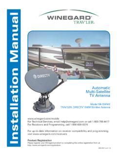
1 1 RoadTrip MinimaxTM Stationary Automatic Satellite TV AntennaModel RT8000S (white dome)Model RT8035S (black dome)WINEGARD Winegard Company 3000 Kirkwood St. Burlington, IA 52601-2000800/788-4417 FAX 319/758-5854 in Winegard Company 2009 2452185 REV3 1/10 Made in the PRODUCT REGISTRATIONP lease register your Winegard product by filling out and returning the Product Registration card provided or by completing the online registration form at also be packaged as: RTS-80W (white dome) or RTS-80B (black dome)2 Parts Included Tools Needed Unpacking the Unit1 Dome 1 base with electronics, dish, dual LNBF*Aftermarket versions also include all mounting hardware and cabling required for a single receiver installationPARTS INCLUDED*:USE 2 PEOPLE when removing the unit from the carton.
2 !DO NOT PAINT DOME! Painting dome will cause signal degradation and will void your NEEDED FOR UNPACKING & INSTALLATION:Level Drill with 3/4 bit1-1/4 hole saw (if mounting switch in wall)Phillips screw driver #23/8 Open end wrench 7/16 Open end wrenchSealant (consult RV manufacturer for proper type for your roof material)Trademarks:Winegard and RoadTrip Minimax are registered trademarks of Winegard Company. DISH Network is a registered trademark of EchoStar Communications Corp. DIRECTV is a registered trademark of Hughes Electronics Corp. All trademarks contained in this manual are property of their respective owners. Reference made to products or services provided by companies, other than Winegard Company, does not represent any endorsement of those products or :Although every effort has been made to insure the information in this manual is correct and complete, no company shall be held liable for any errors or omissions in this manual.
3 Changes and technological advances are continu-ously being made in the Satellite market. Information provided in this manual was accurate at the time of printing. If the RoadTrip Minimax does not function as expected, please contact Winegard Company at (800) 788-4417 or visit our website at Winegard Warranty Information:Attn: Technical ServicesWinegard Company3111 Kirkwood , IA 52601800-788-4417 Fax: 319-758-58541. Open box and remove packing material.!If using knife to open carton, BE CAREFUL. Do not cut the dome on the THE UNIT:2. Lift unit out of box vertically. Do not turn box and roll out, or turn upside down to NETWORK HYBRID1 2 3 4 5 6 7 80 = UP1 = DOWNKEY BELL TV1 2 3 4 5 6 7 8 FIGURE 14.
4 After selecting location for unit (see Step 2), place the unit on the centerline of the vehicle. 5. Position base so that cables exit toward the rear of vehicle. The distance from the edge of the roof to the rear cor-ner of any foot should be at least 12 on both sides of the dish to ensure proper Mode settings are for use in areas where the standard DISH Network settings fail to provide HD Reference Guide This model is PRESET for DIRECTV receivers. If you have a DISH Network or BELL TV receiver, you must change the numbered switches (see figures below).!Install in DRY conditions only!Installing unit on roof of vehicle Obstruction Ht. Unit Clearance8 ..15 10 ..20 12 ..25 15 ..35 IMPORTANT! Do not install this system in the rain, or under any wet conditions.
5 Moisture may affect electron-ics and void your warranty!1. For best performance and to reduce signal acquisi-tion time, park vehicle on a level surface; level the RV. 2. Select a level spot on your roof for installation. WARNING: Level the base front to back and side to side. If base is not level the antenna may require more time to locate the correct Satellite or may not locate the correct Satellite . 3. Ensure proper distance to other rooftop equipment is maintained. Be sure no roof-mounted equipment is blocking the Satellite line of sight ; see chart below. Using this chart, determine the minimum distances to other least 12 At least 12 RoadTrip Minimax MUST Face FRONT of VehicleFIGURE 2 FRONT OF VEHICLEC able connections MUST face REAROBSTRUCTIONUNIT BASE2345TO CHANGE SWITCH SETTINGS FOR DISH NETWORK.
6 SIMPLY MOVE #4 & #7 TO DOWN POSITION (#8 SHOULD REMAIN DOWN ALSO).1 2 3 4 5 6 7 8 DIRECTV DISH NETWORK FACTORY PRESET DIRECTV SWITCH SETTINGS 1 2 3 4 5 6 7 847. Clean roof area where the base feet will be attached to the roof. Do not erase your marks!8. Put approved sealant in the areas marked for the base feet. Place base feet on top of the sealant and screw down with the (3) #10 screws for each foot. 9. After all base feet are secured to roof, put sealant around edge of feet and over screws. 6. Place the unit on the roof in its permanent loca-tion and mark around each base foot, Figure 3. FIGURE 3 Cable entry installation 1. Connect the quick disconnect power cable to the panel mount on the back of the RoadTrip Minimax unit.
7 See Figures 4 & 5 below. POWER PLUG LOCK MAIN Port SECONDARY PortQUICK DISCONNECT SOCKETLOCK (ON TOP OF THE CONNECTOR)FIGURE 4 FIGURE 5!NICKS OR CUTS IN WIRING JACKET MAY CAUSE WATER TO LEAK INTO CABLE CLAMPS COAX CABLE ROUTINGPRIMARY RECEIVERRoAdTRIP MInIMAxSECondARY RECEIVERFIGURE 6 Decide the best location for the power and coax cables to enter the vehicle, and the location of the power switch and receiver. Drill a 3/4 hole in the roof, push wires inside. 2. Connect the Primary receiver to the Primary Port on the panel For a two receiver installation, connect a second coax cable (not provided) to the SECONDARy connector on base and run cable along roof to second receiver Place cable-entry plate over hole and cables.
8 Screw in place. Seal plate and screw holes with approved sealant (not included).5. Depending on the length of the cable on the roof, you may need to use cable clamps or wire ties (not provided) between the unit and your cable-entry plate. Clamping the cable every 12 -16 should eliminate any unnecessary cable movement, Figure 2 & 3 TWO GROUND WIRES 1 FROM VEHICLE 1 BLACK WIRE FROM Satellite DISHSTEPS 4 & 5 RED POWER WIRE FROM DISHSTEPS 6 &7+12 V FROM VEHICLEON/OFF ROCKER SWITCH WITH LIGHT (Shown in OFF position.)FIGURE 7 Connecting TWO receivers1. Connect the coax cable coming from the antenna to the Satellite IN input on the primary receiver. The primary receiver is the receiver used most often and will toggle between Connect the secondary coax cable coming from the antenna to the Satellite IN input on the secondary receiver.
9 NOTE: Secondary receiver will not See page 6 for receiver set-up. Connecting ONE receiver 1. Connect the coax cable from the antenna to the Satellite IN on the receiver. 2. See page 6 for receiver set-up. CONNECTING RECEIVERSINSTALLING THE POWER SWITCH1. Choose a location to install the RoadTrip Minimax power ON/OFF switch. Remember when selecting a location, you will need to run the +12 VDC power cable from the RoadTrip Minimax antenna to the switch. Be sure the switch is in the OFF position before continuing. See Figure 7 or panel mount: Drill 1-1/4 hole, pull wires through wall or Connect the ground wire from the vehicle and the BLACK ground wire from the antenna together, using large yellow flag Connect the YELLOW flag connector to the switch shown in figure 7 Connect the RED wire from the antenna to the small RED flag Connect small RED flag connector to the switch as shown in Figure 7 Connect the +12 V power wire from the vehicle to a small RED flag Connect small RED flag connector to isolated spade on switch.
10 Note: During the RoadTrip Minimax antenna s normal search process, you may hear a slight grinding sound as the unit checks its limits. This is normal and does not harm the your on-screen guide to locate your channel rather than channel surfing . This will result in smoother Turn on receiver and television set. The RoadTrip Minimax antenna must be connected to a receiver that is plugged into 120 Verify that you are getting the receiver s menu screens on the television. These screens are available with or without the dish finding the Turn the power switch on for the RoadTrip Minimax antenna. The dish will detect if it is already on a Satellite signal. If it detects a signal, the dish will move to check it s alternate Satellite and then move back to the original Satellite signal that is If no signal was detected, the dish will begin its search to locate the primary Satellite .