Transcription of Wiring Diagram - Headsets Inc
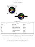
1 To boom mic*New PowerCableExisting Audio/Mic cable9V+( )( )audio +Two GroundsMergeCrossover CableLeft Volume Controlto boom mic*New PowerCableExisting Audio/ Mic cable9V+( )( )audio +Two GroundsMergeCrossover CableLeft Volume ControlFigure AMono Headset with single volume control in left Headset with two volume (9v)Ground (-) (common ground, see below where two grounds merge)Audio (+)Audio (+) after volume controlWiring DiagramAudio Plug(mono)Audio Plug(stereo)Ground (-) Audio +Audio + (R) Audio + (L)Ground (-)This Diagram represents the correct Wiring method to make a Wiring harness and install the anr modules. Five different configurations are shown below. Determine which figure best describes your headset, and installthe modules according to that not assume the colors shown on this schematic represent the colors of the Wiring in your headset prior to to modification.
2 Most Headsets will have different colored Wiring . You must confirm the identity (color) of your audio (+) and ground (-) wires prior to making the Wiring harness. The best way to confirm the identity of audio (+) and ground (-) is with a continuity tester (ohm meter). Your headset may be stereo or mono. Compare your audio plug to the audio plugs shown below to determine if your headset is mono or stereo. Figure B*Leads to the boom mic are not affected and should not be cut or spliced in any manner. Do not usethe boom mic ground lead as a ground for the anr boom mic*New PowerCableExisting Audio/ Mic cable9V+( )( )audio +Two GroundsMergeCrossover Cableto boom mic*New PowerCableExisting Audio/ Mic cable9V+( )( )R audio +Two GroundsMergeCrossover CableLeft Volume ControlL audio +Right Volume controlto boom mic*New PowerCableExisting Audio/ Mic cable9V+( )( )audio +Two GroundsMergeCrossover CableMono Headset with no volume controlsFigure EFigure DFigure CMono Headset with volume control in right side.
3 This layoutrequires a 4 conductorStereo Headset with 2 volume controlsFor technical assistance call 806-358-6336