Transcription of Wiring the TM-1 Mic Adapter - Tigertronics
1 Wiring the TM-1 Mic Adapter grants pass , oregon 154 hillview drive grants pass , oregon 97527 (541) 474-6700 Fax: (541) 474-6703. Introduction: The TM-1 Mic Adapter Kit was created to simplify attaching the TigerTrak to a mobile radio for tracking applications. The Adapter provides a convenient way to connect to the various mic lines without the need to cut or splice any existing Wiring . The Mic Adapter is simply inserted in-line between the radio and the microphone. Inside the Adapter there are a series of jumper terminals that allow you to bridge the appropriate mic lines over to the TM-1 connector. Although this process is simple in theory, it is extremely easy to make an error that could have disastrous consequences! These instructions include a worksheet to guide you through the process. It is important that you read this document thoroughly before beginning and then follow the instructions exactly to insure success.
2 These instructions will take you through the following steps: 1. Assemble the Mic Adapter printed circuit board. 2. Verify the radio's microphone connector pin-out using a multimeter. 3. Make a table showing the correct pin-out of the microphone connector. 4. Complete the jumper wire diagram showing how to install the jumpers. 5. Install the appropriate jumpers on the Mic Adapter circuit board. WARNING: Incorrect Wiring could destroy both the TM-1 and your radio equipment! If after reviewing this document, you are not absolutely certain that you are technically qualified to proceed, we recommend that you obtain the assistance of an experienced technician. Tigertronics assumes no responsibility for the use or misuse of this Adapter . This document is intended only to provide basic guidelines to a qualified technician. It is the sole responsibility of the user to insure proper Wiring .
3 Assembling The PCB: Assembly and soldering of the Mic Adapter circuit board is very straightforward. It is a simple matter of inserting the parts into the board as shown in the pictures below and carefully soldering all the pins. The only caution we might make is to be sure that each component is held tight against the board before you solder. It might be a good idea to solder just one or two pins and then double check the positioning of the part before soldering the remainder. It is extremely difficult to reposition a part after it is completely soldered, so take your time and double check your work! Be sure to index the round connector correctly. Check the connector pin numbers and index notch against the pin numbers and index printed on the board. Interface Cable: The next step in assembling the Mic Adapter Kit is the Wiring of the Interface Cable.
4 This is the cable that connects your radio to the Mic Adapter board. The reason that we want to wire this first is that it provides a useful tool for figuring out the microphone Wiring in the steps that follow. We have provided a short length of eight conductor cable in the kit. The cable already has the RJ-45 connector installed on one end, so you will only need to install the 8-pin round connector on the other. It is best to make this cable as short as possible, so trim it's length appropriately for the distance that you plan to locate the Mic Adapter from your radio. In Wiring the connector, Pin #8 (center pin) is always the most difficult to solder, so we would recommend that you wire the connector pins in sequence starting with Pin #8 (reverse order). Be very careful not to fray any wires as they can cause pins to short when the cable is flexed.
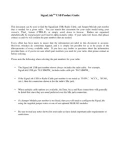
5 It would be best to use heat shrink or insulating tubing on the pins, if it is available. Wire the connector according to the wire colors as shown in the diagram below. 1. G ra y O ra n g e R J -4 5 P lu g B la c k (R e a r V ie w ). R ed 1. 2. 1 8 -P in P lu g 3 (R e a r V ie w ). 8. 7. 4. 8 5 6. G re en Y e llo w B lu e B ro w n M ic A d a p te r R a d io In te rfa c e C a b le - W ire d s tra ig h t-th ro u g h (p in 1 to p in 1 , e tc .). Mic Connector: The next step is to determine for certain the function of each pin on the mic connector. If your radio has a round 8-pin connector the process is very straight forward, but if your radio uses a RJ-45 (telephone like) connector, the process can be a little tricky! To wire either connector you must have the Users Manual for your radio available for reference. To minimize the possibility of making a Wiring mistake, we have provided a Wiring table for you to complete in the Jumper Wire Diagram.
6 As the correct signal is determined for each microphone pin, you should record it in the table. You might want to use a pencil for this process, in case you need to make a change or use the table for a different radio later. If your radio uses the 8-pin round connector, you should be able to copy the signal names and their associated pin numbers directly from the radio manual into the appropriate lines of the Jumper Wire Diagram. When copying this information, be sure that you refer to the actual pin numbers given. Do not attempt to determine the pin number from any illustration of the connector. When you are finished, it would be a good idea to double check the accuracy of your information by testing continuity between chassis ground and the pin that is supposed to be Ground on the connector. If your radio uses an RJ-45 mic connector, you cannot assume that the pin numbers in the manual are listed correctly.
7 If the manufacturer has not followed the industry standard numbering conventions, the lines will be in the correct sequence, but in reverse order (Pin #1 = Pin #8)! Unfortunately this is not at all uncommon. On a number of occasions we have even found disagreement in the numbering system between radio models from the same manufacturer! You should never assume the position of Pin #1 on any RJ type connector, based on the diagram in the manual. Since these lines often times have Accessory Voltage on them, Wiring the connector incorrectly can have catastrophic results! The best way to insure you have the correct Wiring order is to verify with a multimeter where the Ground and PTT pins actually are on the connector. Because the RJ-45 pins are dangerously close together and very fragile, we will use the Interface Cable and Mic Adapter board to help make these tests.
8 Since the adapters RJ-45 and 8-pin round connectors are wired in parallel (Pin #1 = Pin #1), you can use the pins on the back of the boards round connector for testing. These pins are much easier to probe than an RJ-45. pin and are very clearly numbered on the pc board. Turn the radio OFF and attach the Mic Adapter board to your radio using the Interface Cable. Start the identification process by checking for continuity between the radios chassis and the connector pin number that is listed as Chassis Ground in your radio manual. For example: If the manual says that Pin #3 is Ground, then check continuity between the radio chassis and the third pin (Pin #3) on the round connector. When making this measurement, remember that you are looking for Zero Ohms . There will no doubt be some amount of continuity between several other pins, but remember that the one you are testing for is a short to ground!
9 If you don't find continuity on the pin that you tested, then the pin numbers must be reversed in the radio manual. You can verify this by testing the third pin from the other end (in our example Pin #6). You should find continuity on that pin if the order is in fact reversed. If you would like to up your confidence even further, you can turn your radio ON and test the PTT line. Your radio should be attached to an antenna or dummy load for this test, since you will be transmitting briefly. In this test you will be manually keying the transmitter by briefly shorting the PTT line to Ground. If one is available, use a small value resistor (a few hundred ohms) to short the PTT line to Chassis Ground (chassis - not the ground pin). The resistor is not really necessary, but a good idea just in case you are shorting the wrong pin! If the radio transmits, you can be absolutely certain that you have the pin numbering correct.
10 2. Once you have established whether or Mic Adapter RJ-11 Mic Adapter RJ-45 / 8-Pin Rnd not the pins in the manual are listed in reverse order, you should enter the Ground (Pwr) A 1 _____ signal names into the appropriate lines _____ of the Jumper Wire Diagram. If the Acc. Voltage B 2 lines were not reversed, then you can _____ enter the signals exactly as they are PTT C 3. _____ numbered in your radio manual. If the RX Audio D 4 connector numbers were reversed, then _____ enter the signals into Jumper Wire TX Audio E 5. _____ Diagram in the reverse order. This Ground (Mic) F 6 means that the signal listed in the radio _____ manual as Pin #8 should be entered into 7. _____. the Jumper Wire Diagram next to Pin Speaker Input SQ 8 #1. The signal listed in the manual as Pin #7 should be entered into the Jumper Wire Diagram Jumper Wire Diagram as Pin #2 and so on, until all entries are complete.