Transcription of WP eng Estimating Parameters of DC Motors - produktiv …
1 By Ingo V llmecke Estimating Parameters of DC Motors White Paper DC- Motors are used in a wide variety of appli-cations touching our daily lives, where they serve to relieve us of much work. However, the large number of DC- Motors used is attended by a large amount of time and resources devoted to inspecting them at the end of their produc-tion cycle. The time needed for this process should be kept as brief as possible so that the inspection procedure is not the slowest part of the production process. Due to the increasing mass production of these Motors , procedures for inspecting them have been developed which are able to determine the test objects characteristic curves within seconds.
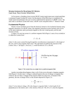
2 Such procedures are known as Parameter Identifica-tion procedures. They determine the parame-ters without applying any external load, simply by measuring the current and voltage. The time and apparatus required for attaching a load and for aligning the test object with a loading mechanism can thus be totally omitted. Introduction: The dynamic behavior of dc motor can be described using two equations. The first equation describes the electrical behavior: The second equation describes the mechanical behavior: where the algebraic symbols represent the following: Note: The load also reflects the moment of static friction inherent in the system.
3 Equations (1) and (2) can now be summarized in a single equivalent electromechanical circuit: Figure 1: Electromechanical equivalent circuit diagram Energy consideration: For a better interpretation of the equations (1) and (2) an energy consideration is now per-formed. Given by the equation (1) is multiplied with the current i and integrated over an indefinite interval. The first term in equation (3) describes the electrical energy supplied, the ohmic losses of the second, the third, the mechanical energy present in the system and the last one, the stored energy in the inductance.
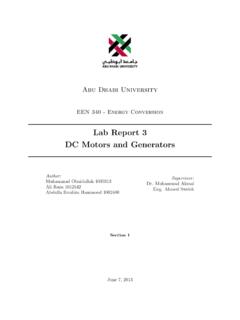
4 The equation (2) is multiplied with the speed and integrated over an indefinite interval. The first term in Equation (4) describes the rotational energy stored in the mechanical system, the second term, the mechanical energy, the third is the speed-proportional losses and the last the discharged mechanical energy loss as well as the energy contained therein due to the static friction. Figure 2: Scheme of the energy distribution. 3 Transfer function of a dc motor Since only the terminal quantities voltage and armature current are used in Estimating a dc motor 's Parameters , the course of the spec-trum of the armature current-to-terminal voltage ratio is of particular interest.
5 On the basis of this transfer function it is possible to make statements about at which point in the frequency range excitation is useful, since relevant parameter changes take effect in that frequency range. A simple example should serve to affirm this: To estimate the Parameters of an electric low-pass with a cutoff frequency of 10 kHz, it insn't a practical approach to excite it with a 10 Hz oscillating quantity, since, considering the measurement precision, the input and output signals are approximately the same (tansfer factor approx.)
6 1, phase-shift between input and output signals approx. 0 degrees). Only if the excitation approaches the cutoff frequency do the filter Parameters become noticeable and is there a chance of determining them with reasonably high accuracy. To determine the transfer function, Equations (1) and (2) are transferred into the Laplace domain. From Equation (5) we thus find the rotational frequency: By using (7) in (5) and making some rear-rangements, we obtain the equation: Equation (8) describes the relationship be-tween the terminal quantites U and I and to the load ML.
7 From equation (8) thus follows: The following simplifications now follow: With these abbreviations, the transfer equa-tion follows: Figure 3: Electrical and mechanical time constant of the DC electric motor . The constant Tele is referred to as the electrical time constant of the DC machine. The electrical time constant is a measure of the response time of the current change in the terminal voltage. The constant Tmech is referred to as the me-chanical time constant of the dc motor . The mechanical time constant is a measure of the RPM's reaction time upon change in the termi-nal voltage.
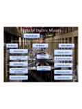
8 Using Equation (9), the DC- motor 's frequency response can be shown for fixed Parameters . 4 The figures below show the frequency re-sponses in terms of both magnitude and phase, as well as the characteristic curve for a motor with given Parameters . Figure 4: Magnitude frequency response of a dc motor . Figure 5: Phase frequency response of a dc motor . Figure 6: Characteristic curve of a dc motor . In addition to the course of the respective frequency responses, the mechanical and electrical time constants are still proportional to frequencies, as well as the locations of the frequencies of the poles of the transfer func-tions.
9 The magnitude frequency response of the dc motor corresponds to a bandpass filter with a center frequency which lies between the two time constants of the motor . The phase fre-quency response of the DC otor corresponds to the phase frequency response of a bandpass filter. The zero in the numerator of the transfer function leads to the phase shift at low fre-quencies to zero. The dc motor in the illustrated example has two real poles in the transfer function. These poles occur as a simple but separate poles in the frequency response.
10 In contrast, there are also Motors with complex conjugate poles, which can be represented in the frequency response as a double pole at the center fre-quency of the bandpass filter. When considering the transfer function, spaces can now be specified in which the dc motor Parameters can be estimated. As indicated above, a function of the zero point is obtained at the bottom of the transfer function in the numerator, but this zero point depends only on the expiry constant. Furthermore, in this re-gion, the magnitude frequency response is near zero, so that there is no meaningful esti-mate that can be carried out and the discharge constant thus can not be determined with reasonable accuracy.