Transcription of Simple Analysis for Brushless DC Motors Case Study: Razor ...
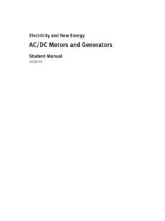
1 Simple Analysis for Brushless DC MotorsCase Study: Razor Scooter Wheel MotorAt first glance, a Brushless direct - current (BLDC) motor might seem more complicated than a permanent magnet brushed dc motor , but the purpose of the following is to emphasize the Simple analytical techniques that can be used to understand the operation of a BLDC motor . The case study is our Razor scooter hub motor , a BLDC motor designed inside a 5 diameter PhysicsElectric Motors transform power from the electrical domain to the mechanical domain using magnetic interaction. In a BLDC motor , this magnetic interaction occurs between coils of wire on the stator (stationary part), permanent magnets on the rotor (rotating part), and the steel structure of single wire carrying current in a uniform magnetic field (Figure 1) sees a force exerted on it, called the Lorentz force:BLIF ,where I is the vector current flowing through the wire (direction is important), L is the length of the wire, and B is the magnetic field vector.
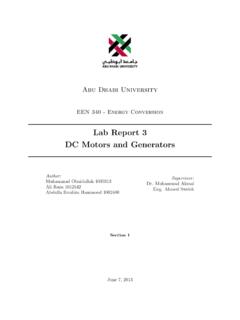
2 The right-hand rule defines the direction of the Lorentz force, F. In Figure 1, the force, F, would therefore be 1N, to the 1: The Lorentz force on a single wire in a uniform magnetic interesting thing happens when a coil of wire moves through a changing magnetic field (Figure 2). In this case, a voltage is induced based on the rate of change in magnetic flux within by the coil. Flux is integral of the magnetic field over some area, so because of the geometry, the rate of change of flux in the scenario depicted by Figure 2 is:vLBdtdV ,whereV is the induced voltage, B is the change in magnetic field, L is the length of coil perpendicular to the motion, and v is the velocity of the coil.
3 The Bis 2T, since the magnetic field shifts from 1T into the page to 1T out of the page. So, for the single coil in Figure 2, the induced voltage is In a motor , this is called the back electromotive force (back EMF).Figure 2: A coil of wire moving through a transition in magnetic ConservationThe Lorentz force law shows that a motor can produce force from current . The flux/voltage relationship shows that it can produce voltage from velocity. (If you spin a motor externally, it can act as a generator.) The key, though, is that the motor is always doing both of these at the same time. A stationary wire produces zero power, no matter how much force is on it. Similarly, a generated voltage produces no power unless current flows through it.
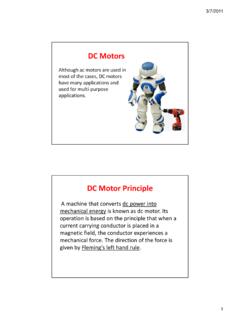
4 Power transfer only occurs when all components voltage, current , force, and velocity are present at the same example, take the same coil as in Figure 2 and now push a 10A current through it in the counterclockwise direction, as shown in Figure 3: The same coil, now with current passing through it as back EMF is still present, since the coil is still moving. But now, a set of Lorentz forces is also present due to the current flowing through both sides of the coil, perpendicular to the magnetic field. The forces are the same as in Figure 1, but there are two since both sides of the coil interact with at 1T magnetic field. The right-hand rule shows that the forces from both sides add, so the total force exerted is 2N, to the the electrical side, whatever is supplying power must push 10A into a system which is generating Since power is just voltage times current , this means that 2W of electrical power is going in.
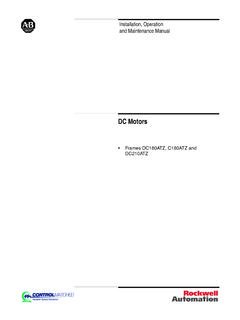
5 From the mechanical side, power is coming out at a rate equal to the force times the velocity. 2N at 1m/s gives a mechanical output power of 2W. The transformation which occurs conserves power. (Losses are taken into account externally, for example by adding the resistance of the coil in series with the drive current .)The power transformation works equally well in both directions. You could reverse the direction of current to create a force that counteracts the velocity, slowing down the motor . This current could supply charge back to the power source in regenerative does this apply to the BLDC Razor scooter wheel?So the question is how that math applies to this:Figure 4: Brushless scooter wheel stator with 2 of 3 , almost directly.
6 The only difference is that there is a bunch of steel in the way. Steel is to magnetic fields as copper is to electric very good conductor. It takes all the current from a coil of wire and concentrates it into a more useful location, such as right underneath a pair of permanent magnets. The length term used above, L, is just the width of the stator teeth, which is 1 , and the current is whatever current we set in the controller. Figure 5shows the windings on a single tooth of the BLDC scooter wheel 5: A single tooth of the BLDC scooter wheel with 30 controller picks which teeth are active according to the position of the rotor. The maximum torque is produced when the active teeth are right between two magnets, which results in a situation very much like Figure 3.
7 The field strength for Neodymium magnets is pretty close to 1T, which makes the math easy. Since there are 30 windings per tooth, 2 teeth per phase, and 2 phases active at any given time, 120 windings contribute to the overall electromagnetic interaction. Ideally, if the steel can carry it, the total current in all the loops combined (1200A) interacts with a 1T field on each side of a tooth. The total force produced by this configuration is therefore given by:.61)1)( )(2)(120)(10(NTmAF This is a pretty high estimate of the force the wheel could produce at 10A. It is direct drive, so there is no need to go through gear ratios, however the outer radius of the wheel is further out than the radius to the magnets.
8 This reduces the force by a factor of about Also, the steel can only carry so much magnetic field before it saturates, so at higher currents the force will not scale linearly. Overall, with 30 windings per tooth, we might expect to see a force at the ground of about 5N (1lbf) per amp of current . This should give pretty reasonably other important parameter is the top speed of the motor . Just as in Figure 3, the moving coils will create a back EMF which will counteract the voltage applied. If the magnets move past the coils at 5m/s then the induced voltage would be given )/5)(120)( )(2( .5m/s is about 11mph. This is the tangential speed of the magnets, though. The tangential speed of the outside radius of the wheel (which is the same as the speed of the scooter) would be a bit higher.
9 This suggests that for a good scooter-like top speed, a 36V system would work. Also, keep in mind that anything which reduces torque (such as flux leakage, larger air gap, poor sensor timing, and magnetic saturation) could increase the speed a bit by weakening the field.(Remember the go-kart?)As a check, we can multiply the current and voltage to see that the input power in this scenario is 305W (about 1/2hp). The output power is 61N times 5m/s, which is also windings don t really convert power with 100% efficiency. They have some resistance that generates heat. (Similarly, the steel will also not conduct the magnetic field perfectly.) To get a rough estimate of the loss in the copper, we can use the rating for 18 AWG magnet wire resistance, which is about 6m per foot, over the length of two phases of windings, which is about 40 feet.
10 This gives a resistance of about . At 10A, the voltage drop in the windings will ) )(10( ,and the power dissipated will be:WARIPdis24) ()10(22 .Compare this to a 25W light bulb. It s a lot of heat, but still less than 10% of the total power converted by the motor . Including other losses, such as in the steel and friction in the bearings, the motor could still be over 80% efficient when running at 10A!TweakingWe probably won t pick the exact right number of turns on the first try, but we can measure the performance of the first motor and use it to tweak the windings. Table 1 shows some possible scenarios and what we might be able to do to accommodate them. Motors are very forgiving, so it s unlikely that we will make a motor that just completely doesn t work, but this will help us figure out how to make it better in just one 1: Possible scenarios after motor testing and the course of action that could be Course of ActionWhy?