Transcription of WWAR-OM1-3 WW Air Release Valve - Val-Matic …
1 manual No. WWAR-OM1-3 Val-Matic Wastewater Air Release Valve Models 48A, 49A Operation, Maintenance and Installation manual INTRODUCTION .. 1 RECEIVING AND STORAGE .. 1 DESCRIPTION OF OPERATION .. 1 INSTALLATION .. 2 Valve CONSTRUCTION .. 2 MAINTENANCE .. 3 TROUBLESHOOTING .. 4 DISASSEMBLY .. 4 REASSEMBLY .. 4 PARTS & SERVICE .. 5 WARRANTY .. 6 Val-Matic Valve AND MANUFACTURING CORP. 905 Riverside Dr. Elmhurst, IL 60126 Phone (630) 941-7600 Fax (630) 941-8042 1 Val-Matic 'S WASTEWATER AIR Release Valve OPERATION, MAINTENANCE AND INSTALLATION INTRODUCTION This manual will provide you with the information to properly install and maintain the Valve to ensure a long service life. The Wastewater Air Release Valve has been designed with stainless steel trim to give years of trouble-free operation but regular maintenance is recommended for valves subject to fluids containing suspended solids or greases/oils.
2 The Wastewater Air Release Valve is typically mounted at the high points in a piping system to automatically remove pockets of air as they accumulate. The Valve can also be used to slowly Release air in tanks and pump casings. The Valve is a float-operated, resilient-seated Valve designed to handle waste fluids. The Valve may be equipped with backwash accessories. The Size, Maximum Working Pressure and Model No. are stamped on the nameplate for reference. Note: Low Durometer seats are available for low pressure applications. RECEIVING AND STORAGE Inspect valves upon receipt for damage in shipment. Handle all valves carefully without dropping. valves should remain boxed, clean and dry until installed to prevent weather related damage. For long term storage greater than six months, the Valve must remain in the box and stored indoors.
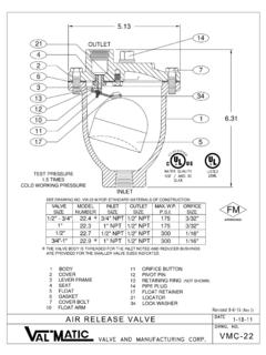
3 Do not expose Valve to sunlight or ozone for any extended period. DESCRIPTION OF OPERATION The Wastewater Air Release Valve is designed to automatically remove air pockets at the high points in a piping system. The Valve , as shipped, is a normally open Valve and will slowly vent air through the top orifice. As fluid enters the Valve , the float will rise, closing the orifice. As air accumulates in the piping system and enters the Valve , the float drops allowing the venting orifice to open. The Valve can be equipped with optional external valves and hose connections for backwashing. These items are packaged separately. FIGURE 1. WASTEWATER AIR Release Valve The lever mechanism provides mechanical advantage for the float. During system operation, the pipeline pressure exerts a strong upward force on the sealing component, the orifice button.
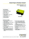
4 The lever mechanism magnifies the weight of the float so that the orifice will open under high pipeline pressures. Additional ports are provided for flushing, testing and draining purposes. CAUTION This Valve is not intended for fuel liquids service. 2 CAUTION Install Valve with INLET port down or leakage will occur ITEM DESCRIPTION MATERIAL 1 Body Cast Iron 2 Cover Cast Iron 3 Leverage Frame* Stainless Steel 4 Seat* Stainless Steel 5 Float* Stainless Steel 6 Gasket* Non-Asbestos 7 Cover Bolt Alloy Steel 8 Retaining Screw* Stainless Steel 10 Float Arm* Stainless Steel 11 Orifice Button* Buna-N 12 Pivot Pin* Stainless Steel 13 Retaining Ring* Stainless Steel 14 Pipe Plug Iron 17 Float Retainer* Stainless Steel 18 Lock Nut* Stainless Steel 19 Link* Stainless Steel 20 Extension Shaft* Stainless Steel 21 Locating Pin Stainless Steel 22 Orifice Button Arm* Stainless Steel 28 Pipe Plug Malleable Iron 30 Washer*
5 Stainless Steel 33 Clevis* Stainless Steel 34 Lock Washer* Stainless Steel 35 Retaining Screw* Stainless Steel 36 Pipe Plug Malleable Iron *RECOMMENDED REPAIR PART KIT INSTALLATION The installation of the Valve is important for its proper operation. valves must be installed at the system high points in the vertical position with the inlet down. For pipeline service, a vault with freeze protection, adequate screened venting, and drainage should be provided. During closure, some fluid discharge will occur so vent lines should extend to an open drain area in plant service. A shut-off Valve should be installed below the Valve in the event servicing is required. Valve CONSTRUCTION The standard Wastewater Air Release Valve body and cover are cast iron.
6 See the specific Materials List submitted for the order if other than standard cast iron construction. All internal components are stainless steel with the exception of the orifice button which is resilient. The general details of construction are illustrated in Figure 2. The body (1) is threaded for connection to the pipeline. The seat (4) is threaded into the cast cover (2). TABLE 1. LIST OF PARTS FIGURE 2. WASTEWATER AIR Release Valve 3 WARNING Wear safety glasses to look into the Valve outlet after installation. Released fluid can cause injury. Option Backwash Assembly Refer to the drawing on page 3 for the correct piping arrangement. Please note the each Kit contains extra fittings such as reducer bushings that may not be needed for your Valve . The fittings should be installed with a standard pipe compound such as Oatey White Thread Sealant (supplied) or sealing tape.
7 The quick disconnect fittings are designed for easy push and turn connections to a clean water source. MAINTENANCE The Wastewater Air Release Valve should be scheduled for regular inspection on an annual basis. Based on experience in service, a more frequent backwash regimen may be desirable to minimize leakage. Inspection: Periodic inspection to verify operation can be performed. The Valve should not leak fluid at any connection or through the outlet. If there is leakage through the outlet, perform a backwash procedure on the Valve . Check to see that air is being released by cracking open the lower drain Valve . If a large amount of air is released from the drain Valve , then the main Valve may be clogged and cleaning or a backwash procedure should be performed. Lubrication: The Wastewater Air Release Valve is a self-contained automatic Valve and does not require and lubrication to enhance its operation.
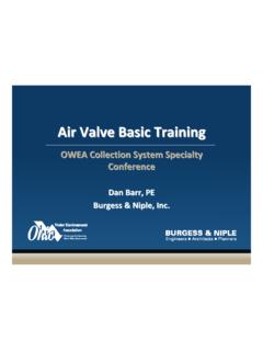
8 Tools: No special tools are needed to maintain or repair the Valve . The Valve can be equipped with backwash valves and hoses for ease of backwashing. Backwash Procedure: In order to properly backwash the Valve , a " clean water supply of at least 30 psi is needed. This supply should be connected to the rubber hose with quick disconnect couplings as provided with the wastewater Valve and shown in Figure 3. 1. Pipe Valve B to a drain prior to backwashing. 2. Close inlet Valve A. 3. Open Valve B. 4. Connect water supply to E and supply water for 3 minutes to flush seat and mechanism area. 5. Re-connect water supply to C and open Valve D to wash the Valve body for 1 minute. 6. Close valves D and B. 7. Slowly open Valve A to place unit back in service. FIGURE 3.
9 BACKWASH HARDWARE Backwash Accessory Kits Type Inlet Backwash Kit Valve Models Air Release Valve 2 SPK-48 ABW 48 ABW, 49 ABW, 3 , , 4 , , 4 WARNING The Valve must be drained before removing the cover or pressure may be released causing injury. TROUBLESHOOTING Several problems and solutions are presented below to assist you in troubleshooting the Valve assembly in an efficient manner. Leakage at Bottom Connection: Tighten Valve threaded connection. If leak persists, remove Valve and seal threads with Teflon* sealant. Leakage at Cover: Tighten bolts per Table 2, replace gasket. Valve Leaks when Closed: Backwash Valve to remove debris. Disassemble and inspect seat, orifice button, and float. NOTE: Many floats contain sand for weight but if water is detected, replace float.
10 Valve not Venting Air: Check that operating pressure does not exceed Working Pressure on nameplate. Backwash Valve . DISASSEMBLY The Valve can be disassembled without removing it from the pipeline. Or for convenience, the Valve can be removed from the line. All work on the Valve should be performed by a skilled mechanic with proper tools. No special tools are required. 1. Close inlet shut-off Valve . Open drain Valve or remove drain plug. Remove the cover bolts (7) on the top cover. 2. Pry cover (2) loose and lift off Valve body. 3. Remove the 2 retainer rings (13) and pivot pins (12) that pass through the lever frame (3). The float (5) and linkage will be free from the cover. Disconnect float from lever (10). DISASSEMBLY (Cont'd) 4. To remove lever frame (3), remove two round-head fasteners (8).