Transcription of X-Plane 11
1 1 X-Plane 11 Cirrus SF50 Pilot s Operating Manual Author: Julian Lockwood Copyright: Laminar Research 2020 Disclaimer The information contained in this document is for simulation use only, within the X-Plane flight simulator. This document is not subject to revision and has not been checked for accuracy. This document is intended for entertainment only and may not to be used in situations involving real-life aircraft, or real-life aviation. Distribution This document may be copied and distributed by Laminar Research customers and developers, for entertainment. It may also be distributed with third-party content developed for X-Plane 11. 2 Contents Background: The Cirrus SF50 .. 4 Cirrus SF50 Specifications .. 5 The X-Plane SF50 .. 6 Views and Controls .. 7 Creating Quick Look views .. 8 Operating the controls .. 11 Assigning peripheral devices.
2 13 A Tour of the Cockpit .. 15 Overhead Panel .. 15 Display Panels .. 16 Primary Flight Display (PFD) .. 16 Multi-Function Display (MFD) .. 17 Audio Panel Display .. 17 Weight and Balance Display .. 18 Systems Display .. 18 [PFD] Controls & 19 [MFD] Controls & Features .. 24 Center Pedestal .. 28 Thrust Lever .. 28 Flap Lever .. 29 Fuel Control Switch .. 29 Autopilot Control Panel .. 30 Autopilot Operation .. 31 ILS Approach .. 33 Set the Nav1 or Nav2 frequency for the ILS approach .. 33 The Course Deviation Indicator (CDI) .. 34 The Glide Slope Indicator and Vertical Speed Pointer .. 34 Autopilot Assisted ILS Approach .. 35 Flight Planning .. 36 Fuel Calculation .. 37 Load Sheet Tables .. 37 PAYLOAD: EMPTY .. 38 3 PAYLOAD: MEDIUM .. 38 PAYLOAD: FULL .. 38 Setting the Weight, Balance and Fuel in X-Plane .. 39 Checklists .. 40 Pre-Flight Exterior Inspection.
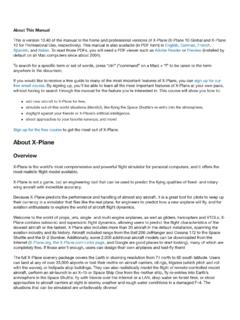
3 40 Cold and Dark to Engine Start .. 42 Before Taxi .. 46 Before 49 After Takeoff .. 50 Cruise .. 52 Before Landing .. 53 Landing .. 54 After Landing .. 55 Parking .. 57 Operating-Speeds .. 61 4 Background: The Cirrus SF50 The Cirrus Vision SF50 is a very light jet originally designed and manufactured by Cirrus Aircraft, based in Minnesota, USA. A mock-up of the aircraft was first revealed in 2007, and a prototype followed in 2008. The maiden flight was made on 3rd July 2008, but development ceased shortly afterwards due to lack of funding. In 2011, Cirrus was purchased by China Aviation Industry General Aircraft (CAIGA) and development resumed. A new prototype flew in 2014, followed shortly by two more. After a test-flight program, the FAA awarded a type certificate in October 2016. The aircraft is powered by a single Williams FJ33 turbofan, and features an all-composite construction, and a pressurized cabin.
4 Cruising speed is 300 knots (560 km/h) and range is approximately 1,200 nautical miles (2,200 km). A whole-aircraft ballistic parachute system is fitted for emergencies. 5 Cirrus SF50 Specifications Engines: Model ---------------------------------------- - 1 x Williams FJ33 turbofan Power ---------------------------------------- - 1 x 1,800 lbf ( kN) thrust Fuel: Capacity ---------------------------------------- - 2,000 pounds (910 kg). Fuel ---------------------------------------- - Jet A-1 Fuel Burn * ---------------------------------------- - 462 (210 kg/h) at max cruise 315 lb. (143 kg/h) at economical cruise Weights and Capacities: Max. Takeoff Weight ---------------------------------------- - 6,000 lbs. / 2,722 kg. Max. Landing Weight ---------------------------------------- - 5,550 lbs. / 2,517 kg. Empty Operating Weight ---------------------------------------- - 3,636 lbs.
5 / 1,649 kg. Useful Payload ---------------------------------------- - 2,300 lbs. / 1,134 kg. Maximum Passengers ---------------------------------------- - 5 Performance: Max. Cruise Speed ---------------------------------------- - 308 KTAS Long Range Cruise Speed ---------------------------------------- - 300 KTAS Final Approach Speed ---------------------------------------- - 95 KTAS (full flap/gear down) Minimum Takeoff Distance* ---------------------------------------- - 2,036 ft. / 621 m Minimum Landing Distance* ---------------------------------------- - 1,721 ft. / 525 m Range ---------------------------------------- - 1,312 nm Service Ceiling ---------------------------------------- - 28,000 ft. / 8,534 m Representative value depending on conditions 6 The X-Plane SF50 Unlike other flight simulators, X-Plane employs a technique called blade element theory.
6 This utilizes the actual shape of the aircraft (as modeled in the simulator) and breaks down the forces on each part separately. The force of the air acting on each component of the model is individually calculated, and combined, to produce extremely realistic flight. When you fly an airplane in X-Plane , there are no artificial rules in place to govern how the aircraft behaves. Your control inputs move the control surfaces of the aircraft, and these interact with the virtual flow of air around it. As such, you may consider that you are really flying the aircraft. Due to the use of Blade Element Theory in X-Plane , an aircraft must be modeled with great accuracy, in order that it behaves like its real-life counterpart. This means the fuselage, wings and tail surfaces must be the right size and shape, the center of lift and center of gravity must be in the right places, and the engine(s) must develop the right amount of power.
7 In fact, there are a great many properties that must be modeled correctly to achieve a high-fidelity flight model. The SF50 featured in X-Plane -11 has been modeled by our design team with a degree of accuracy that ensures its flight characteristics are like the real aircraft. However, despite this, some differences will be apparent, because even the smallest factor plays into the ultimate behavior of the aircraft in reality, and in X-Plane . The systems modeling of this aircraft involves some compromise too, because of the degree of complexity present in the real aircraft. However, in many cases, the actual SF50 procedures could be followed when operating the X-Plane version. Checklists are presented later in this document (with modifications to suit this specific simulation platform and model). It is recommended that X-Plane pilots follow those procedures to extract the maximum capability and enjoyment from this aircraft.
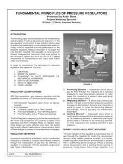
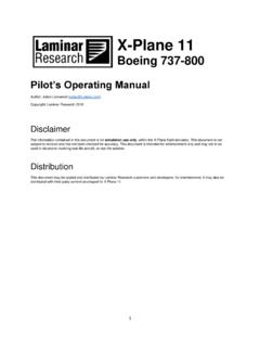
8 7 Views and Controls The X-Plane SF50 features a detailed 3-D cockpit with many of the primary controls and systems modeled, including: Flight controls (yoke, rudder pedals, thrust levers, prop levers, condition levers), electrical systems, pneumatic systems, navigation aids, radios, autopilot, interior and exterior lighting, and fuel systems. 8 Creating Quick Look views Before discussing the controls, we suggest that the pilot establish a series of Quick Look views that will be helpful later when interacting with this particular aircraft. If you are not familiar with this technique, more information is available in the X-Plane Desktop Manual. The following Quick Look views are recommended for the SF50, in a situation where the pilot is not using a Virtual Reality (VR) headset, or a head tracking device. To some degree, these correspond (on the keyboard Number Pad) with their physical locations in the cockpit - and are therefore logical and easy to recall later.
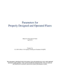
9 Engine Control Panel Primary Flight Display (PFD) Thrust Lever and Center Console 9 Multi-Function Display (MFD) Pilot s View Forward Systems Panel & Autopilot Co-Pilot s View Forward 10 Left Glance View Overhead Panel Right Glance View 11 Operating the controls This section covers the basic techniques for the operation of the controls that you will encounter in the cockpit of an X-Plane aircraft. Control manipulators are consistent across all X-Plane 11 aircraft. However, the specific illustrations in THIS chapter may differ from YOUR aircraft. Toggle and Rocker switches are operated with a single click of the mouse. Place the mouse pointer slightly above, or below, the center point of the switch, depending on the direction you intend to move it. A small white arrow is displayed to confirm the intended direction.
10 Click the mouse button to complete the operation. Levers are operated by assigning a peripheral device to the necessary axes in X-Plane (throttle, prop, mixture etc.). More information is available in the X-Plane Desktop Manual. Levers may also be operated by clicking and dragging the mouse pointer. Some rotary dials are operated by positioning the mouse pointer on top of the control, and then a click and drag to the right, or to the left. The same can be accomplished using the mouse wheel - if one is present on your device. Other rotary controls require finer precision. When the mouse pointer is positioned slightly to the left of such a control, a counter-clockwise arrow appears. This indicates that you are ready to rotate the control counter-clockwise. Correspondingly, a clockwise arrow indicates that you are ready to rotate the control clockwise.