Transcription of XBC 10-65 - EcoSmart Classic (ES) or Basic (BC) Controls ...
1 XBOXER XBC. UNIT SIZES 10 - 65 WITH. EcoSmart Classic (ES) OR Basic CONTROL (BC). INSTALLATION, OPERATING AND. MAINTENANCE INSTRUCTIONS. IN THE. DE. ErP. MA. UK. FOR THE COMPLETE VENTILATION SOLUTION. MA. UK. COMPLIANT DE. 2016 IN THE. XBOXER XBC 10-65 (ES & BC Controls ). The EMC Directive Supply & Extract Ventilation Unit with Heat Recovery 2014/30/EU. The Low Voltage Directive Installation and Maintenance 2014/35/EU. Introduction Code description: XBOXER XBC Ventilation Unit The information contained in this document provides details of XBC 45 - H - L - ES - WP - R - BA. installation, operation and maintenance for installers and users of | | | | | | | |. the XBOXER XBC Supply and Extract Ventilation Unit with Heat 1 2 3 4 5 6 7 8. Recovery. 1. XBOXER XBC Range 2. Unit size 10, 15, 25, 45, 55 and 65. This supply and extract air handling unit range comprises an combination of high efficiency centrifugal fans with EC motors, a 3.
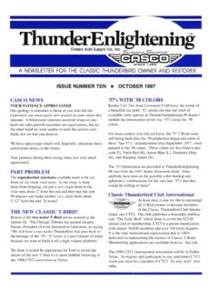
2 H = Horizontal Side by Side layout Counterflow design plate heat exchanger, filters, optional heaters 4. N = No Heater (LPHW and Electric) and a casing with high mass acoustic treatment. L = LPHW Heater E = Electric Heater A range of matched, close coupled attenuators with a similar 5. ES = EcoSmart Control construction method to that of the unit is available. The attenuators BC = Basic Control can be flipped for positioning on the left or right of the fan unit 6. WP = Separate Matched Weather Roof if required (see Figure 1) allowing flexibility for duct layout. 7. R = Opposite arrangement (control box, heater battery and Attenuators are available in 1050, 1250 and 1600mm lengths and a condensate pipe connection on opposite side). matching attenuator flange is attached to the fan unit. 8. BA = Bottom access (filter only, see section ). CP = Constant Pressure General information regarding performance and specifications for the equipment may be obtained from our Technical Literature, and/or Code description: Matched Combined Attenuator project specific documentation.
3 XBC 25 - HS - MS10. | | | |. 1 2 3 4. 1. XBOXER XBC Range 2. Unit size 10, 15, 25, 45, 55 and 65. 3. HS = Horizontal Supply/Discharge Attenuator Figure 1. Layout Overview of the XBC unit viewed from above and HE = Horizontal Extract/Intake Attenuator shown with matched room side and atmospheric side attenuators. 4. MS10 = 1050mm Attenuator Access for maintenance and inspection of the standard XBOXER XBC MS12 = 1050mm Attenuator units is from the side of the unit. MS16 = 1050mm Attenuator Atmospheric side Intake / Discharge Attenuator: 1050 / 1250 / 160 0 mm long (optional). Attenuator/Flange Attenuator/Flange connector connector XBC Unit Room Side Extract / Supply Attenuator: Access to Intake Filter /. 1050 / 1250 / 1600mm long (optional) Fan / Condensate tray and Pump *. Access to Controls *. Access to Coil bleed and drain /. Valve / Valve Actuator /. Electric Heater Elements *. Access to Extract FIlter / Fan *.
4 Duct Connection Blanking Panel *Unlock an access panel by inserting a flat head screwdriver into the locking latch and turning anti-clockwise (1/4 turn). Note: Bottom access unit (BA) Filters cannot be accessed from the side of the unit. 029 2085 8400 04. 10. 18. Leaflet Number 671605. 2. Installation and Maintenance XBC 10-65 EcoSmart Classic (ES) & Basic (BC) Controls XBOXER XBC Unit Access Concepts code: XBC15-H-LES BA), provide access to filters only (see Figure 6). In this product range, several unique concepts have been Filter removal is not available from the sides on these units. Bottom implemented with a view to simplifying the installation design. access units must be installed with the following minimum clearance below the units. 1. The unit configuration is such that the supply and discharge connections are positioned on the unit centre line. XBC15 = 225mm, XBC25 = 300mm XBC45 = 360mm. The corresponding Intake and Extract connections may be positioned Note: Bottom access is not available on XBC55 or XBC65 units.
5 On either side of the unit, allowing greater flexibility in the layout of ductwork in the space, (Figure 3) with the blanking panel re-positioned Figure 2. The control side of the unit must be installed with at least to suit. 250mm clearance from a wall / barrier to gain access from the side. 2. The standard EcoSmart XBC unit configuration is shown in Figure 4. Filter removal from internal frame Unit handing information will not be requested for this range, and units will be supplied in this format as standard. Access covers on control side 3. The unit must be installed with at least 250mm clearance from a of fan unit wall / barrier. With this absolute minimum clearance, the unit may be connected to the power supply and control connections since the control may be rotated by 90 degrees to face downwards. (Note: - cable connections must allow for the relative movement when the control is re-positioned). 4.
6 With this clearance, unit filters may be changed, and the fans coils, heat exchanger and condensate tray may be inspected and cleaned if necessary. Hinged EcoSmart & Basic control box rotates 90 o 5. The LPHW and Electrical heater settings, coil bleed and drain, and all to assist with other control adjustments are similarly accessible (see Figure 1). commissioning. 6. Side access, where possible, is preferred in all cases in terms of safe working access to the equipment under the CDM regulations. 250mm clearance for access 7. Note however, that access in the situation is difficult and does not allow for major maintenance including component replacement. Nuaire IMPORTANT. recommend as best practice guidance, to allow for a minimum of around 600mm clearance (as stated in ADF 2010). Unlocking an access panel is achieved by inserting a flat head screwdriver into the locking latch groove and turning anti-clockwise 8.
7 Where these arrangements are not suitable, the Consultant's (1/4 turn), keys are neither required nor provided by Nuaire. and Contractor's project specific requirements will always be accommodated where Bottom access only units (Example Figure 3. Selectable Duct Connections (Top view). Figure 5. Opposite unit arrangement (R) side access (Top view). Plan view Filter Counterflow Plate Heat Exchanger Plan view Filter Counterflow Plate Heat Exchanger Blanking Blanking Extract Intake plate plate Position 2. Position 1. Supply Discharge Discharge Supply (Fixed) (Fixed) (Fixed) (Fixed). Extract Intake Intake Extract Position 1. Position 2. Position 2. Position 1. Control Coil connections Coil connections LPHW or Electric Heater Battery LPHW or Electric Heater Battery Note: The unit is shipped with four G4 filters in place, two of which are included as spares. For F7 filters contact Nuaire. Figure 4. Standard Unit Format (Top view).)
8 Figure 6. Bottom access only unit (Example code: XBC15-H-LES-BA). Plan view Filter Counterflow Plate Heat Exchanger Filter access Filter access Blanking Blanking plate plate Supply Discharge (Fixed) (Fixed). Extract Intake Position 1. Position 2. Control Filter access Filter access LPHW or Electric Heater Battery 029 2085 8400 04. 10. 18. Leaflet Number 671605. 3. Installation and Maintenance XBC 10-65 EcoSmart Classic (ES) & Basic (BC) Controls IMPORTANT Storage The equipment must be stored in a dry, internal location. Ductwork Safety first! Before commencing any work ensure: connection apertures shall be sealed against the ingress of dust, water That all appropriate risk assessments have been carried out and the and vermin. required safety measures have been taken. That you understand the work required. If the storage period is to exceed two months, contact Nuaire for That you are trained and competent to carry it out.
9 Guidance on the appropriate mothballing procedures. Do not stack units, modules or components. Delivery of Equipment Erection and Assembly Receipt of equipment Units must be installed in accordance with good industry practice. All equipment is inspected prior to despatch and leaves the factory in These units may only be mounted horizontally and must be fully good condition. Upon receipt of the equipment an inspection should be levelled in the horizontal plane. The units are heavy, and should be made and any damage indicated on the delivery note. mounted using the fixing brackets supplied or other suitable methods Particulars of damage and/or incomplete delivery should be endorsed of support. The supporting structure must be assessed for structural suitability. by the driver delivering the goods before offloading by the purchaser. Heat recovery components and modules that incorporate cooling No responsibility will be accepted for damage sustained during the coils may produce condensation during use.
10 An insulated drip tray and offloading from the vehicle or on the site thereafter. condensate pump is provided. The drain connection must be connected All claims for damage and/or incomplete delivery must be reported to to a suitable drainage point (see Figure 22 on page 13 for details). Nuaire within two days of receipt of the equipment. Condensate Pump Alarm Offloading and Handling from the delivery Vehicle The condensate pump incorporates an alarm function. If the water The weight of the unit modules and palletised items is displayed on level in the condensate tray exceeds a maximum level (for example, as the unit rating plate or on the packaging. Some of the modules have an a result of the discharge tube becoming blocked or frozen), the alarm uneven weight distribution, and this will be indicated by labelling where contact will open. This contact is internally connected to the heat appropriate. Ensure that lifting and handling equipment is adequately exchanger bypass actuator, and the unit will automatically be placed rated.