Transcription of Your 2 Meter Mobile Antenna – What’s the Best Mounting ...
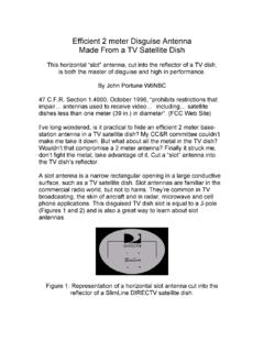
1 QST Devoted Entirely to Amateur Radio March 2012 1the car, with wires spaced less than a 1 4 wave-length apart. It was built in the WIRES function of EZNEC. Note that this model is made of far more than the 25 segments supported by the demo version of EZNEC. This requires either of two purchased ver-sions of the program, EZNEC+ or EZNEC PRO. These allow for the large number of wire segments used in the model. A wire spacing of less than 1 4 wavelength makes the wire-frame appear as a solid metal surface to the model. My first model was of a 3 4 ton standard pickup truck with a metal toolbox. Here it s for an average sedan measuring 15 6 5 feet (LWH) and 6 inches off the ground. See Figure 2 (red outline).
2 I sim-plified the car s shape as shown to make the wire-frame easier to construct (black outline). This causes only tiny differences in the radiation mention the pickup truck only because the patterns are quite similar to those of the sedan. This suggests that the results are valid for a wide variety of vehicles. Readers who are familiar with using EZNEC may find it enlightening to repeat the process for a van or an RV, either metal skinned or of partially synthetic construction. You may dis-cover that some common Antenna Mounting maxims need another Surfaces OnlyWhile my first version of the sedan s wire-frame included both top and side surfaces, I later I found that the vertical surfaces have almost no effect on the radiation patterns.
3 Therefore, I dropped them from wire frame. This allowed me to use my available segment count to define a closer wire spacing that pro-vides improved Radiation PatternsFigure 3 shows the results the hori-zontal (azimuth) patterns of a 1 4 wave D oes it matter where you put a dual band 2 Meter and 70 cm Antenna on your car? Some may say, Who cares, I only work local repeaters and rarely do simplex? Well just the other day I heard a local ham bemoaning, I wish I could talk to my regular repeater better from this location. Perhaps he could if he d just move his Antenna to a different spot on his car. Perhaps you haven t thought about it because you never saw a systematic technical comparison of the results of car Antenna Mounting positions.
4 Hams normally just consider appearance and conve-nience. But there is a better method. This basic analysis may change your opinion. This simple, yet system-atic, look at Antenna placement uses radiation patterns gener-ated by EZNEC, a respected PC Antenna modeling program that pro-vides a friendly input/output language for the Numerical Electromagnetic It is a simple-to-use but powerful tool that has opened my eyes about many antennas over the years. We ll model a typical 2 Meter , 19 inch whip at five popular locations on a car: 1) roof top, dead center, 2) roof top, side, 3) rear window, top, center (glass mount), 4) trunk lid, dead center and 5) trunk lid, side, front. The relative results are also valid for a higher-gain Antenna or a dual band Antenna while used on 2 meters .
5 To evaluate a VHF/UHF Antenna on a car, we only need to look at the horizontal (azi- your 2 Meter Mobile Antenna What s the Best Mounting Location?Where you mount that Antenna makes a difference. Antenna modeling gives us some Portune, W6 NBC1 Several versions of EZNEC Antenna modeling software are available from developer Roy Lewallen, W7EL, at 1 Side view of EZNEC model of sedan. Details of the wire grid are shown in Figure ) radiation patterns. EZNEC generates vertical (elevation) patterns as well, but in these cases they are all very similar, indicat-ing little about the best Mounting locations. The Wire-Frame ModelThe first step was to construct a wire-frame model of the vehicle to mount the Antenna on.
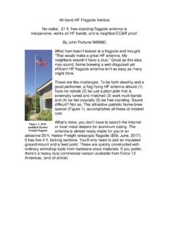
6 It is a rectangular grid of wires in the shape of 2 March 2012 ARRL the national association for Amateur Radio Figure 3 Elevation plot of a 2 Meter whip mounted at the dead center of the roof (red) over average soil, compared to the same configuration over a perfect ground plane (black). Note the loss of low angle radiation more than a full Meter whip at the five common loca-tions. They are actual EZNEC plots just graphically simplified for clarity. In each plot I ve also included a reference Antenna . It too is a 19 inch long whip, but mounted over a perfect ground plane, not over the wire frame. As theory predicts, its pattern is omnidirec-tional (the outer circle). The dotted scales of each figure are in relative dB.
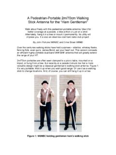
7 (The front of the sedan is to the right.) The dotted scales are dBi (EZNEC s usual output), that is, gain compared to an isotropic radiator. I adjusted each plot to the same scale to provide a uniform comparison of all five and the reference Antenna . From these plots we can now derive some very useful guidelines for installing a Mobile VHF/UHF Antenna . Three seem evident to me. If readers see others, I would appreciate hearing from you. Antenna Mounting Rules of Thumb There are always lobes. Even though a car s body is large enough to provide an efficient ground plane for a VHF Antenna , the azimuth pattern is never truly omnidirectional, as is evident from the plots. Note the lobes, and in particular notice the 2 S-unit (12 dB) Figure 2 EZNEC azimuth patterns of 1 4 wave 2 Meter whip antennas mounted at various locations on a wire grid model of the sedan shown in Figure 1.
8 As shown, the center of the top provides the best pattern, followed by the center of the trunk strength difference, direction to direction. To give a practical use of this, in a weak signal area of a repeater s coverage, knowing where the gain and loss is relative to your car, can make a big difference. By simply mov-ing your Antenna , a troublesome dead spot on a regular commute may vanish without any significant compromise to repeater access in other areas. This is what the ham above needed to know. Center is better. Figure 3 illustrates the disadvantage of Mounting an Antenna off the center line of the vehicle either side to side or front to back. The reason? Off-center locations always create relative gain, dia-metrically across the vehicle, and also loss on the same side.
9 Transmitter hunters, for example, often use this pattern phenomenon. On HF trans-mitter hunts, directional antennas are much too large to mount on a car. But with only a simple HF whip mounted at an end of the rear bumper normally the poorest Mounting location they can find the stron-gest signal direction by simply driving their cars in small circles. For this application, the pattern lobes are an advantage. For the usual 2 Meter /70 cm Mobile instal-lation, chose an on-center location if possible. This can be on any one of your vehicle s large horizontal surfaces, such as the trunk lid or the roof top. Notice the non-symmetry of the patterns from off-center locations. This to me is the most valuable rule of thumb of this little analysis.
10 Higher is better. The figures also demonstrate the value of a higher mount-ing position. Surprisingly, though, it isn t as much of a factor as some hams may believe. Therefore, also using the rule above, a lower on-center position is often better than a higher off-center location. I have not even bothered to show an end of the bumper mount, as the transmitter hunters use. The radiation pattern there has the largest Own PreferenceOn my pickup truck, a work vehicle, I located the VHF/UHF Antenna in the dead center of the roof top. Here, where appear-ance is not a big concern, it is the best choice. On my family sedan, I usually pre-fer dead center of the trunk lid. A magnetic roof mount in the middle of the roof is also good, though less attractive.