Bending Moment Design
Found 10 free book(s)
Combined Bending and Axial Loads
user.engineering.uiowa.edubending moment Mu have been recognized as the practical procedure for design. • Axial compression strength requirement Required axial strength ≤ Design axial strength of the section u c n ≤φP P, or 1 u cn P φP ≤ • Bending moment strength requirement Required bending strength ≤ Design bending strength of the section u b n ≤φM M ...

R.C.C WATER TANKS
www.gn.dronacharya.info3)DESIGN OF BASE SLAB:- Specification Size Reinforcement details Base slab Short span I. -ve bending moment II. +ve bending moment Long span I. -ve bending moment II. +ve bending moment 5m×4m 16mm Ø @80mm c/c 16mm Ø @110mm c/c 16mm Ø @110mm c/c 10mm Ø @220mm c/c 30
SLAB DESIGN - Memphis
www.ce.memphis.edu5. Design beams if any, using procedures you learned in CIVL 4135. Positive and Negative Distribution of Moments For interior spans, the total static moment is apportioned between critical positive and negative bending sections as (See ACI 318-02 Sect. 13.6.3): Panel Moment Mo 100% Static Moment Negative Moment Mo negative Mu = 0.65 Mo Positive ...

BEAM DESIGN FORMULAS WITH SHEAR AND MOMENT
engineering.purdue.eduJan 06, 2005 · Shear and moment diagrams and formulas are excerpted from the Western Woods Use Book, 4th edition, and are provided herein as a courtesy of Western Wood Products Association. Introduction Notations Relative to “Shear and Moment Diagrams” E = modulus of elasticity, psi I = moment of inertia, in.4 L = span length of the bending member, ft.
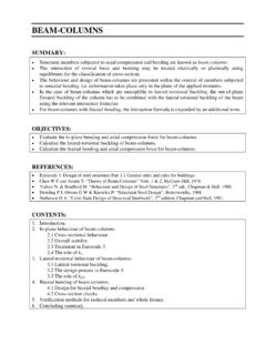
BEAM-COLUMNS
www.labciv.eng.uerj.br• The interaction of normal force and bending may be treated elastically or plastically using equilibrium for the classification of cross-section. • The behaviour and design of beam-columns are presented within the context of members subjected to uniaxial bending, i.e. deformation takes place only in the plane of the applied moments.

Design of Composite Beams with Large weB openings
www.steelconstruction.infodesign bending moment at the centreline of an opening bending resistance of the composite section at the centreline of an opening plastic bending resistance (of Tee section) bending resistance of the top Tee, reduced for axial tension and shear design bending moment in
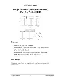
Design of Beams (Flexural Members) (Part 5 of AISC/LRFD)
user.engineering.uiowa.edu53:134 Structural Design II My = the maximum moment that brings the beam to the point of yielding For plastic analysis, the bending stress everywhere in the section is Fy , the plastic moment is a F Z A M F p y ⎟ = y 2 Mp = plastic moment A = total cross-sectional area a = distance between the resultant tension and compression forces on the cross-section a A

Chapter 2. Design of Beams – Flexure and Shear
www.egr.msu.eduCE 405: Design of Steel Structures – Prof. Dr. A. Varma • In Figure 4, My is the moment corresponding to first yield and Mp is the plastic moment capacity of the cross-section. - The ratio of Mp to My is called as the shape factor f for the section. - For a rectangular section, f is equal to 1.5. For a wide-flange section, f is equal to 1.1. ...

Cross sectional Shape Selection
cecs.wright.eduME 474-674 Winter 2008 Slides 9 -5 Elastic Bending I = Moment of inertia of the cross section Table 11.2 gives the section properties of different shapes For a circular cross section If S is the stiffness for another shape with the same cross sectional area made of the same material and subject to the same loading, then the shape factor for elastic bending is defined as
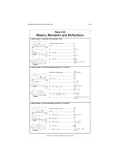
BEAM DIAGRAMS AND FORMULAS
www-classes.usc.edu3-216 DESIGN OF FLEXURAL MEMBERS Table 3-23 {continued) Shears, Moments and Deflections 10. SIMPLE BEAM-TWO EQUAL CONCENTRATED LOADS UNSYMMETRICALLY PLACED