Voltaje
Found 8 free book(s)
2 3 VOLTAJE CORRIENTE Y RESISTENCIA
tecnica4chiautempan.edu.mxLa fuente de voltaje ideal no existe pero pue- de ser aproximada en la práctica. Se supondrá ideal a menos que se especifique lo contrario. Las fuentes de voltaje pueden ser de cd o de ca. Un símbolo común para una fuente de volta- je de cd se muestra en la figura 2-12(a), y uno para una fuente de voltaje de ca lo indica la parte (b).
Lecture 20 - Massachusetts Institute of Technology
web.mit.edu6.012 Spring 2007 2 1. Common-drain amplifier • A voltage buffer takes the input voltage which may have a relatively large Thevenin resistance and replicates the

1 3 Dell Thunderbolt Dock
downloads.dell.comDell Thunderbolt™ Dock WD19TB Quick Start Guide 3 4 NOTE: Computers requiring more than 130 W power input must also be connected to their own power adapter for charging and operating at full performance. 1 2 Important You must update your computer’s BIOS and the

1 3 Dell Thunderbolt Dock
downloads.dell.comDell Thunderbolt™ Dock WD19TBS Quick Start Guide 3 4 NOTE: Computers requiring more than 130 W power input must also be connected to their own power adapter for charging and operating at full performance. 1 2 Important You must update your computer’s BIOS and the
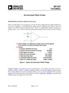
MT-037: Op Amp Input Offset Voltage - Analog Devices
www.analog.comMT-037 TUTORIAL. Op Amp Input Offset Voltage . DEFINITION OF INPUT OFFSET VOLTAGE . Ideally, if both inputs of an op amp are at exactly the same voltage, then the output should be at

MT-041: Op Amp Input and Output Common-Mode and ...
www.analog.comMT-041. At the output, VOUT has two rail-imposed limits, one high or close to +VS, and one low, or close to –VS.Going high, it can range from an upper saturation limit of +VS –VSAT(HI) as a positive maximum. For example if +VS is 5 V, and VSAT(HI) is 100 mV, the upper VOUT limit or positive maximum is 4.9 V. Similarly, going low it can range from a lower saturation limit of –VS +

ICL8038 - Massachusetts Institute of Technology
www.mit.edu3 Sine Wave Amplitude VSINE RSINE = 100kΩ 0.2 0.22 - 0.2 0.22 - 0.2 0.22 - xVSUPPLY THD THD RS = 1MΩ (Note 4) - 2.0 5 - 1.5 3 - 1.0 1.5 % THD Adjusted THD Use Figure 4 - 1.5 - - 1.0 - - 0.8 - % NOTES: 2. RA and RB currents not included. 3. VSUPPLY = 20V; RA and RB
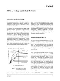
Introduction: The Nature of VCRs - Vishay Intertechnology
www.vishay.comAN105 Siliconix 10-Mar-97 1 Introduction: The Nature of VCRs A voltage-controlled resistor (VCR) may be defined as a three-terminal variable resistor where the resistance val-