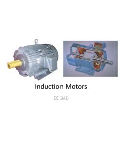
3-Phase Induction Motors
The 3-phase stator coils are placed 120o apart. Once connected to the source, the currents in three coils will be ... Power flow diagram 3 [ (1 ) / ] 3 3 ( / ) 3 / 3 2 2 2 2 2 2 2 2 2 2 1 1 2 1 P P P I R S S P I R P I R S p E R P I R v AG L L AG e C L Simplified per-phase equivalent circuit
Download 3-Phase Induction Motors

Information
Domain:
Source:
Link to this page:
Documents from same domain

Power Semiconductor Switching Devices
www.egr.unlv.eduClassification of power semiconductor switches ... • The MCT is a power switch with a MOS gate for turn- on and turn-off. It

Power Semiconductor Switching Devices - …
www.egr.unlv.eduIdeal controllable Power Semiconductor Switch • When turned on, current can flow only in the direction of the arrow

EE 340 Spring 2011 - Howard R. Hughes College of …
www.egr.unlv.eduConstruction of synchronous machines In a synchronous generator, a DC current is applied to the rotor winding producing a rotor magnetic field.
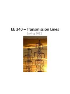
EE 340 – Transmission Lines
www.egr.unlv.eduElectrical Characteristics • Transmission lines are characterized by a series resistance, inductance, and shunt capacitance per unit length. • These values determine the power-carrying capacity of the

Mechanics of Materials - University of Nevada, Las Vegas
www.egr.unlv.eduME 302 Materials Mechanics Introduction and Overview This is a fundamental course in all Civil and Mechanical Engineering Programs. Sometimes it is called:

Resonant Converters - University of Nevada, Las Vegas
www.egr.unlv.edu9-12 ZCS Resonant-Switch Converter By controlling the switch-off time (t 4 - t 3), i.e., the switching frequency, the average value of v oi, hence the average power supplied to the load

PowerPoint Presentation
www.egr.unlv.eduThe Laplace Transform Theorem: Initial Value If the function f(t) and its first derivative are Laplace transformable and f(t) Has the Laplace transform F(s), and the exists, then

Sunlight and its Properties - Howard R. Hughes College of ...
www.egr.unlv.eduTypes of Radiations • Scattered sunlight (what makes the sky blue) is responsible for the light entering the north-facing windows. It is referred to as diffuse radiation.
Magnetic Circuits - UNLV
www.egr.unlv.eduAmpère in 1826) relates the integrated magnetic field around a closed loop to the electric current passing through the loop. where H is the magnetic field intensity (measured in At/m) • At a distance r from the wire, ³ H .dl I ³ H .dl H .( 2Sr ) I
Obtain the z parameters for the network in Fig. 19.65.
www.egr.unlv.edu* Find the impedance parameter equivalent of the network in Fig. 19.66. Figure 19.66 For Prob. 19.2. * An asterisk indicates a challenging problem. Chapter 19, Solution 2. Consider the circuit in Fig. (a) to get z11 and z21. 1 Ω I2 = 0 + V1 − 1 Ω I1 (a) Io + V2 − Io' 1 Ω 1 Ω 1 Ω 1 Ω 1 Ω 1 Ω
Related documents
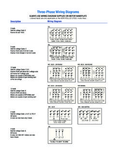
Three-Phase Wiring Diagrams
catalog.wegelectric.comThree-Phase Wiring Diagrams ALWAYS USE WIRING DIAGRAM SUPPLIED ON MOTOR NAMEPLATE - colored leads are only applicable on the NEW ROLLED STEEL motor lines - Single-Phase Wiring Diagrams ALWAYS USE WIRING DIAGRAM SUPPLIED ON MOTOR NAMEPLATE FOR MOTORS WITH THERMAL PROTECTION
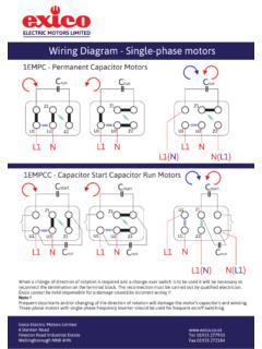
Wiring Diagram - Single-phase motors
www.sentridge.comWiring Diagram - Single-phase motors 1EMPC - Permanent Capacitor Motors 1EMPCC - Capacitor Start Capacitor Run Motors ELECTRIC MOTORS LIMITED When a change of direction of rotation is required and a change-over switch is to be used it will be necessary to reconnect the termination on the terminal block.
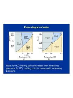
Phase diagram of water - Columbia University
www.columbia.eduPhase diagram of water Note: for H2O melting point decreases with increasing pressure, for CO2 melting point increases with increasing pressure. WATER Covers ~ 70% of the earth’s surface Life on earth depends on water Water is a “universal” solvent Easily polluted; hard to purify.

Typical Electrical Drawing Symbols and Conventions.
www.nrc.govBasics 6 7.2 kV 3-Line Diagram : Basics 7 4.16 kV 3-Line Diagram : Basics 8 AOV Elementary & Block Diagram : Basics 9 4.16 kV Pump Schematic : Basics 10 480 V Pump Schematic : Basics 11 MOV Schematic (with Block included) Basics 12 12-/208 VAC Panel Diagram : Basics 13 Valve Limit Switch Legend : Basics 14 AOV Schematic (with Block included)
MIDTERM #2: INFORMATION SYSTEMS (INDE499B) Dr. …
courses.washington.eduthat identifies the phases of data design and includes the following information for each phase: a). a description of the data design phase, b). the inputs of the phase, c). the outputs of the phase, d). a key issue addressed in the phase e). a challenge that …
Introduction to Alloy Phase Diagrams
www.asminternational.orgsystem, the phase diagram usually has the general appearance of that shown in Fig. 3. The diagram consists of two single-phase fields separated by a two-phase field. The boundary between the liquid field and the two-phase field in Fig. 3 is called the liquidus; that between the two-phase field and solid field is the solidus.

FIELD ORIENTED CONTROL 3-PHASE AC-MOTORS
www.ti.comThe following diagram shows the stator current complex space vector: a iS b c ia α2i c αib Figure 1: Stator current space vector and its component in (a,b,c) where (a,b,c) are the three phase system axes. This current space vector depicts the three phase sinusoidal system. It still needs to be transformed into a two time invariant co-ordinate ...
Fe-C Diagram
staff.emu.edu.trcooled down from a temperature within the g-phase region (e.g., at 800 ºC). • Initially the alloy is composed entirely of the austenitic phase having a composition of 0.83 wt% C • As the alloy is cooled, no changes will occur until the eutectoid temperature (727 ºC). • Upon crossing this temperature to point B, the austenite
Three-Phase Wiring Diagrams
catalog.wegelectric.comThree-Phase Wiring Diagrams ALWAYS USE WIRING DIAGRAM SUPPLIED ON MOTOR NAMEPLATE - colored leads are only applicable on the NEW ROLLED STEEL motor lines - Single-Phase Wiring Diagrams ALWAYS USE WIRING DIAGRAM SUPPLIED ON MOTOR NAMEPLATE FOR MOTORS WITH THERMAL PROTECTION

Phase Diagrams States of Matter and Phase Changes
www.montgomery.k12.ky.usTerminology of Phase Diagrams Critical Temperature and Critical Pressure This is the point on the phase diagram above which a liquid is unable to form. It cannot form because the particles have TOO much kinetic energy to form intermolecular bonds needed for liquids.