Advanced Calibration Techniques for Vector Network Analyzers
measurement. The network analyzer hardware is optimized for speed, yielding swept measurements that are must faster than those obtained from the use of an individual source and an individual receiver like a spectrum analyzer. Through calibration, VNAs provide the highest level of accuracy for measuring RF components.
Download Advanced Calibration Techniques for Vector Network Analyzers

Information
Domain:
Source:
Link to this page:
Documents from same domain
IEEE TRANSACTIONS ON APPLIED SUPERCONDUCTIVITY, …
anlage.umd.eduIEEE TRANSACTIONS ON APPLIED SUPERCONDUCTIVITY, VOL. 27, NO. 4, JUNE 2017 1502204 Superconductive Ultracompact Magnetically Coupled Resonator With Twin-Spiral Structure
Understanding VNA Calibration - UMD
anlage.umd.eduThese parameters control the digital filtering and post¬processing that determine the effective noise floor, amount of trace noise and, in some special cases, immunity to interfering signals. The trade off for improved noise performance is slower sweep speed. Figure 3-1 provides an example of two IF-bandwidth settings. Settings
Agilent De-embedding and Embedding S-Parameter …
anlage.umd.edusolution is to use a test fixture that interfaces the coaxial and non-coax-ial transmission lines. The large variety of printed circuit transmission lines makes it difficult to create test equipment that can eas-ily interface to all the different types and dimensions of microstrip and coplanar transmission lines1 (Figure 1). The test equipment ...
Related documents
Spike Spectrum Analyzer Software User Manual
signalhound.comJan 06, 2022 · o A TG series device can only be interfaced when a compatible spectrum analyzer is connected in the Spike software. This document will guide users through the setup and operation of the software. Users can use this document to learn what types of measurements the software is capable of, how to perform these
Detection and Measurement of Radar Signals: A Tutorial
www.its.bldrdoc.govthe spectrum analyzer input is +10 dBm with 50 dB of internal spectrum analyzer attenuation invoked at the front end, then the amount of attenuation that needs to be inserted between the coupler output and the spectrum analyzer input is (90–20–50–10) = 10 dB.

BASICS OF THE SPECTRUM ANALYZER - UC Santa Barbara
web.ece.ucsb.edumeasurements. 3 Spectrum Analyzer Controls In this section we shall describe some of the basic controls on the spectrum analyzer that you will frequently use. More details on these, and descriptions of the more obscure controls, can be found in the user manual. Mainly, you will use the three large buttons labeled FREQUENCY,
Application Note AN043 - Texas Instruments
www.ti.comThe output power was measured using max hold on a spectrum analyzer. CC2511 was programmed for 0 dBm output power and the antenna was horizontally oriented and directed towards the receiving antenna. This corresponds to 0° in the XY plane on Figure 6. The bandwidth measurements were not performed with a correction factor on the spectrum …
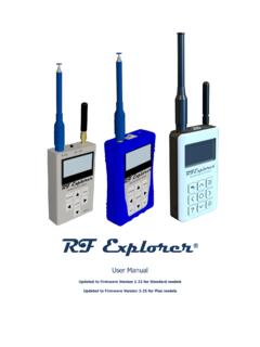
RF Explorer Spectrum Analyzer User Manual
j3.rf-explorer.comRF Explorer is an affordable Handheld Spectrum Analyzer with a growing list of features. This little powerful unit is the tool you need to reduce the implementation time and cost of your next wireless project. Updates of the RF Explorer User Manual are available online. Please consider the environment before printing this document.

FieldFox Handheld Analyzers 4/6.5/9/14/18/26.5/32/44/50 GHz
www.keysight.comJan 13, 2022 · NOTE: Combination analyzers = Cable and antenna tester (CAT) + Vector network analyzer (VNA) + Spectrum analyzer (SA) Frequency specifications Models Frequency range N991xA, N992xA N9913A 30 kHz to 4 GHz N9913A-V5K 5 kHz to 4 GHz N9914A 30 kHz to 6.5 GHz N9914A-V5K 5 kHz to 6.5 GHz N9915A, N9925A 30 kHz to 9 GHz N9915A-V5K 5 kHz to …
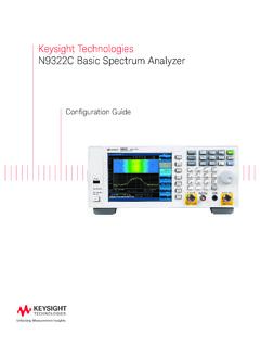
Keysight Technologies N9322C Basic Spectrum Analyzer
www.farnell.comIBOC2 measurements 1. DANL: Displayed average noise level 2. BOC: In-band On-channel Step 2. Add spectrum analysis features Description Option number Additional information Time-gated spectrum analysis N9322C-TMG Measures any one of several signals separated in time, or excludes periodic interfering signals Signal monitor with spectro-
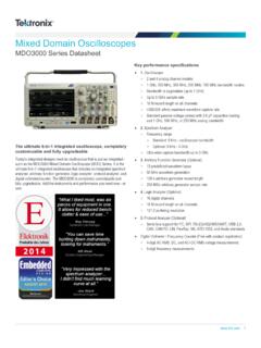
Mixed Domain Oscilloscopes - Farnell
www.farnell.comultimate 6-in-1 integrated oscilloscope that includes an integrated spectrum analyzer, arbitrary function generator, logic analyzer, protocol analyzer, and digital voltmeter/counter. The MDO3000 is completely customizable and fully upgradeable. Add the instruments and performance you need now - or later. Key performance specifications 1 ...

Spurious Emission Measurement on 3GPP Base Station ...
cdn.rohde-schwarz.comsignal. The spectrum analyzer needs to handle the peak amplitudes of the signal 8 to 12 dB higher than the mean power. This application note explains the requirements for spurious emission measurements according to the 3GPP standards (TS25.104 and TS25.141). The parameters of the spectrum analyzer affecting its dynamic range are

Radiated Spurious Emission Testing
www.ewh.ieee.orgReceiver vs. Spectrum analyzer Spurious Emission measurements differ from EMI measurements mainly in that BW’s matching the useful signal have to be set on the receiver instead of the typical EMC bandwidths (e.g. 200 Hz, 9 kHz, 120 kHz). Also EMC BW’s are referred to the 6 dB points of the IF filters,