Transcription of Radiated Spurious Emission Testing
1 Radiated Spurious Emission Testing Garth D Abreu Jari Vikstedt What is RSE? RSE = Radiated Spurious Emission Radiated chamber Emission EMI Spurious intentional radiator 2 Spurious Spurious , all emissions but the fundamental (carrier) Spurious can be harmonics, oscillations, mixing terms 3 GHz GHz GHz GHz GHz GHz GHz GHz GHz GHz Satellite TV Ultra Wide Band WiMAX b/g Spurious Spurious Domain 4 Receiver vs. spectrum analyzer Spurious Emission measurements differ from EMI measurements mainly in that BW s matching the useful signal have to be set on the receiver instead of the typical EMC bandwidths ( 200 Hz, 9 kHz, 120 kHz).
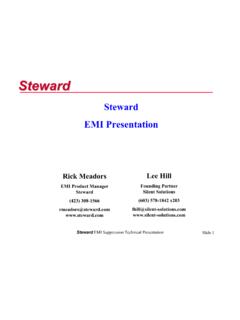
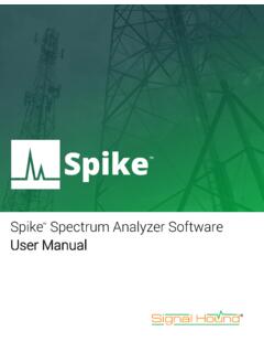
2 Also EMC BW s are referred to the 6 dB points of the IF filters, whereas the BW s for Spurious Emission measurements are referred to the 3 dB points. In Spurious Emission measurements, the peak detector takes the place of the QP detector. All these differences make it necessary that for Spurious Emission measurements a spectrum analyzer or test receiver with spectrum analyzer functionality to be used rather than a pure EMC test receiver 5 Typical RSE Standards FCC 15C/22/24/ (90) Per and of TIA-603-C/D 3 GPP standards define RSE for cellular technologies, such as for GSM (same std as EN 400 367-1) ETSI EN 300 328 defines RSE for GHz ISM band using spread spectrum modulation, up to 24 GHz ETSI EN 300 440 even defines RSE for equipments used to 40 GHz, Spurious measured to 100 GHz Limit lines are given in dBm, not dBuV This implies EIRP measurement EIRP not function of test distance So, substitution calibration is required 6 Semi Anechoic Chamber 7 3m Test Distance high 1 to 4 m scan high FCC Chamber 8 FCC does not deviate from general ANSI spec when measuring the RSE, but simply reinforces the use of typical 3-meter EMC chamber.
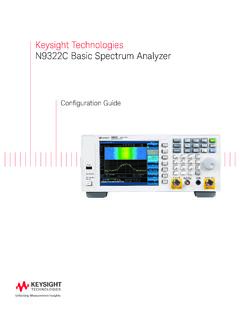
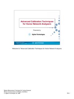
3 Noise Floor in FCC 3 meter chamber 9 3m distance Short cable Receive antenna 10dB horn with built-in preamp ETSI Chamber 10 The above mentioned standards (ETSI 300-328, ETSI 300-440) clearly define the Reflectivity of absorber and chamber size, not chamber performance. ETSI Chamber 11 FCC Intentional Emitters: f < 10 GHz: to the tenth harmonic of the highest fundamental frequency or to 40 GHz, whichever is lower. In some cases the emissions from an intentional radiator must be measured to beyond the tenth harmonic of the highest fundamental frequency designed to be emitted by the intentional radiator because of the incorporation of a digital device. FCC Rules Part 22 and 24 requirement for Radiated Spurious emissions is as follows: The ERP limit is 13dBm [derived from 43 +10log(P)] 12 FCC RBW/Limits 13 FCC Spurious Testing , Handset Example 1.
4 Connect the equipment with the EUT s antenna in a horizontal orientation. If antenna element can be loaded with 50 ohm dummy load please do so or else take care not to overload the receiver/ spectrum analyzer . 2. Adjust the settings of the Radio Communication Tester to set the EUT to its maximum power at the required channel. NOTE, Requires communication antenna to maintain the link! 3. Set the spectrum analyzer to measure peak hold. 4. Place the measurement antenna in a horizontal orientation. Raise the measurement from 1m up to 4 meters in steps and rotate the EUT 360 degrees at each height to maximize all emissions . Measure and record all Spurious emissions (LVL) up to the tenth harmonic of the carrier frequency.
5 5. Replace the EUT with a horizontally polarized half wave dipole or known gain antenna. The center of the antenna should be at the same location as the center of the EUT s antenna. Step is typically performed prior to Testing and LOSS is recorded by test software 14 FCC Spurious Testing , Handset Example 6. Connect the antenna to a signal generator with known output power and record the path loss in dB (LOSS). LOSS = Generator Output Power (dBm) analyzer reading (dBm). Step is typically performed prior to Testing and LOSS is recorded by test software 7. Determine the level of Spurious emissions using the following equation: Spurious (dBm) = LVL (dBm) + LOSS (dB): 8.
6 Repeat steps 4, 5 and 6 with all antennas vertically polarized. 9. Measurements are to be performed with the EUT set to the low, middle and high channel of each frequency band. 15 FCC Emission limitations for cellular equipment The rules in this section govern the spectral characteristics of emissions in the Cellular Radiotelephone Service. (a) Out of band emissions . The power of any Emission outside of the authorized operating frequency ranges must be attenuated below the transmitting power (P) by a factor of at least 43 + 10 log(P) dB. (b) measurement procedure. Compliance with these provisions is based on the use of measurement instrumentation employing a resolution bandwidth of 100 kHz or greater.
7 In the 1 MHz bands immediately outside and adjacent to the frequency block a resolution bandwidth of at least one percent of the Emission bandwidth of the fundamental Emission of the transmitter may be employed. A narrower resolution bandwidth is permitted in all cases to improve measurement accuracy provided the measured power is integrated over the full required measurement bandwidth ( 100 kHz of 1 percent of Emission bandwidth, as specified). The Emission bandwidth is defined as the width of the signal between two points, one below the carrier center frequency and one above the carrier center frequency, outside of which all emissions are attenuated at least 26 dB below the transmitter power.
8 16 FCC Emission limitations for Broadband PCS equipment. The rules in this section govern the spectral characteristics of emissions in the Broadband Personal Communications Service. (a) Out of band emissions . The power of any Emission outside of the authorized operating frequency ranges must be attenuated below the transmitting power (P) by a factor of at least 43 + 10 log(P) dB. (b) measurement procedure. Compliance with these provisions is based on the use of measurement instrumentation employing a resolution bandwidth of 1 MHz or greater. However, in the 1 MHz bands immediately outside and adjacent to the frequency block a resolution bandwidth of at least one percent of the Emission bandwidth of the fundamental Emission of the transmitter may be employed.
9 A narrower resolution bandwidth is permitted in all cases to improve measurement accuracy provided the measured power is integrated over the full required measurement bandwidth ( 100 kHz of 1 percent of Emission bandwidth, as specified). The Emission bandwidth is defined as the width of the signal between two points, one below the carrier center frequency and one above the carrier center frequency, outside of which all emissions are attenuated at least 26 dB below the transmitter power. 17 Example of FCC Spurious Test 18 Uplink Signal ETSI Standard Basics 19 EMI measured from 30 MHz to The receiving device is spectrum analyzer (3dB BW RBW), not EMI receiver (6dB BW RBW).
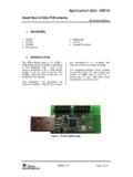
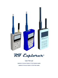
10 No defined chamber performance test Only absorber requirement And suggested chamber size (10m x 5m x 5m) ETSI RBW/VBW Settings 20 Here is to given one example. ETSI Limits 21 Harmonics are mostly limited to -30dBm (in dBd), or (in dBi) [dBd = dBi ] Basic ETSI RSE System Diagram 22 3D positioner for 3D measurement Notch Filter to remove fundamental carrier Preamp to increase dynamic range Notch Filter Preamp Filters for Wireless Compliant EMC Solution For measurement of the radiation and sensitivity of wireless devices under different signal protocols and frequency. Main carrier frequencies used are: 800 MHz, 900 MHz, , .. When measuring broadband responses these carrier frequencies need to be included in the measurement path.