Analog to Digital Conversion
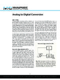
Voltage-to-frequency converters inherently have a high noise rejection characteristic, because the input signal is effectively integrated over the counting interval. Voltage-to-frequency conversion is commonly used to convert slow and noisy signals. Voltage-to-frequency ADCs are also widely used for remote sensing in noisy environments.
Download Analog to Digital Conversion

Information
Domain:
Source:
Link to this page:
Documents from same domain
Analog to Digital Conversion - Measurement …
www.mccdaq.com2 Measurement Computing • 10 Commerce Way • Norton, MA 02766 • (508) 946-5100 • info@mccdaq.com • mccdaq.com Voltage-to-Frequency ADCs
Data Acquisition Fundamentals - Measurement …
www.mccdaq.comPage 4 Measurement Computing | 1-800-234-4232 | info@mccdaq.com | mccdaq.com coeffi cient, which in turn depends on the chemical composition

USB Voltage and Current Output Devices
www.mccdaq.comMeasurement Computing 3(50) 46-5100 info@mccdaq.com mccdaq.com USB-3100 Series Block Diagrams Microcontroller DIO 8 Channels SPI Full-Speed USB 2.0 Compliant Interface SYNCLD 1 1 ...
Fundamental Signal Conditioning - Measurement …
www.mccdaq.com3 Measurement Computing • 10 Commerce Way • Norton, MA 02766 • (508) 946-5100 • info@mccdaq.com • mccdaq.com A – + R f 100 kW 0 A
Noise Reduction and Isolation - mccdaq.com
www.mccdaq.comMeasurement Computing • 10 Commerce Way • Norton, MA 02766 • (508) 946-5100 • info@mccdaq.com • mccdaq.com 1 Hot phase A

Saving DASYLab data to an ASCII (text) readable file
www.mccdaq.comDASYLab Techniques Saving DASYLab data to an ASCII (text) readable file Updated to reflect changes in DASYLab 2016 (V14) The DASYLab Getting Started Guide (Manual.pdf is included on the CD and in the Windows Start menu) provides
Fundamental Signal Conditioning - mccdaq.com
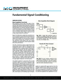
www.mccdaq.comfollower and the difference amplifier. Inverting Amplifier Stages The inverter stage is the most basic operational amplifier configuration. It simply accepts an input signal referenced to common, amplifies it, and inverts the polarity at the output terminals. The open-loop gain of a typical operational amplifier is in the hundreds of thousands.

DASYLab - mccdaq.com
www.mccdaq.comDASYLab 2020 . dasylab.com . DASYLab 2020 . Data Acquisition, Controlling, and Monitoring . Sept 2019 324212E-01
Data Acquisition Handbook
www.mccdaq.comMeasurement Computing (508) 946-5100 info@mccdaq.com mccdaq.com Measurement Computing (508) 946-5100 info@mccdaq.com mccdaq.com Data Acquisition Handbook v …
Related documents
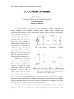
DC-DC Power Converters
ecee.colorado.edu120 V or 240 V ac utility voltage is rectified, producing a dc voltage of approximately 170 V or 340 V, respectively. A dc-dc converter then reduces the voltage to the regulated 5 V or 3.3 V required by the processor ICs. High efficiency is invariably required, since cooling of inefficient power converters is difficult and expensive.

Doubly fed induction generator uising back-to-back PWM ...
web.mit.eduThe converters used are standard 7.5 kW commercial bipolar transistor PWM inverters with a rated DC-link voltage of 580V and a maximum switching frequency of 1 kHz. At this power level, the use of IGBT convert- ers would have allowed a higher switching frequency and would have eased some of the control-loop design.
LECTURE 34 HIGH FREQUENCY TRANSFORMER
www.engr.colostate.eduHIGH FREQUENCY TRANSFORMER A. Transformer Basics 1. Geometry of Cu Wire Windings and Core Wire ... accurately treat the case of an inductor which carries only AC currents in part B. Previously we treated only the filter inductor, which had small ... Forward converters in the range of 50 to 500 Watts, half-bridge from 100 to l000 Watts, and full ...

ON Semiconductor Is Now
www.onsemi.combridge converter. One is resonant frequency at operating mode #1, shown in Figure 9 operating mode #1: Rac=0. The resonant frequency of mode #1 is expressed by Equation 2. In the vicinity of fr1, output voltage is equal or less than input voltage. f r1 1 2 Lr Cr (eq. 2) The other frequency is the resonant frequency at operating mode #2, shown ...
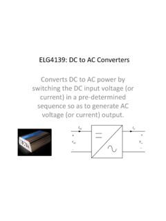
DC to AC Converters Inverters - Engineering
www.site.uottawa.caOutput of the inverter is “chopped AC voltage with zero DC component”. It contain harmonics. An LC section low-pass filter is normally fitted at the inverter output to reduce the high frequency harmonics. In some applications such as UPS, “high purity” sine wave output is required. Good filtering is a must.

Demystifying Type II and Type III Compensators Using Op ...
www.ti.comvoltage-mode control in CCM where there is a large phase drop just after the resonant frequency. Type II compensators are usually reserved for current-mode control compensation, or for converters that always operate in the DCM region. T Gain (dB) 0 20 40 60 80 Frequency (Hz) 10 100 1k 10k 100 k 1M Phase [deg]-90-80-70-60-50-40-30-20 R 1,C 1 R 2 ...
Survey of Resonant Converter Topologies
www.ti.comconverters rely on frequency modulation (FM) to achieve voltage or current regulation instead of traditional pulse width modulation (PWM). Therefore, the input-to-output voltage gain of a resonant converter can no longer be derived from the inductor volt-second balance like PWM converters and becomes much more complex than a PWM converter.