
Chapter 11 Differential Amplifier Circuits
If two input voltage are equal, the differential amplifier gives output voltage of almost zero volt. If two input voltages are not equal, the differential amplifier gives a high output voltage. Let’s define differential input voltage V in(d) as V in(d) = V in1 – V in2 and common-mode input voltage V in(c) = 2 Vin 1 +Vin 2. From these ...
Download Chapter 11 Differential Amplifier Circuits

Information
Domain:
Source:
Link to this page:
Documents from same domain

Chapter 4 Junction Field Effect Transistor Theory …
staff.utar.edu.my4 Junction Field Effect Transistor Theory and Applications - 114 - Between point A and B, it is the ohmic region of the JFET. It is the region where the voltage and current relationship follows ohm's law.

Chapter 16 Oscillator Circuits and Applications
staff.utar.edu.mywhere A V is the voltage gain of the amplifier and β = V Vout f is the feedback ... Many oscillators are designed utilizing RC network and resistor divider circuits. RC network is basically used to determine the resonant frequency of the oscillator, whilst resistor divider circuit is used to provide attenuated feedback. ...
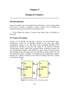
Chapter 9 Design of Counters - Universiti Tunku Abdul Rahman
staff.utar.edu.my09 Design of Counters - 116 - Based on the results obtained from the Karnaugh maps, the circuit design of synchronous decade counter is shown in Fig. 9.15. Figure 9.15: A synchronous decade counter designed using JK flip-flop 9.4.2 Design of an …

Chapter 5 Physics of MOSFET and MOSFET Modeling
staff.utar.edu.my5 Physics of MOSFET and MOSFET Modeling - 88 - where N A is the acceptor doping concentration for p-type semiconductor, ni is the intrinsic carrier concentration and kT/q is the thermal voltage. Substituting equation (5.2) into equation (5.1) yields equation (5.3).

Chapter 16 Fourier Series Analysis
staff.utar.edu.myA rectified half sine wave is defined over one period f(t) = Asin ωt for 0 < t < T/2 and f(t) = 0 for T/2 < t < T as shown in Fig. 16.1. Find the Fourier series of this wave form. Figure 16.1: A half-wave rectifier Solution The dc voltage shall be a 0 = ∫ ω + ∫ T T / 2 T / 2 0 0dt T 1 Asin tdt T 1 = π = − ω ω − A 1 2 T cos T A. The
Related documents

Operational Amplifier Circuits - MIT OpenCourseWare
ocw.mit.eduA voltage to current (V-I) converter accepts as an input a voltage Vin and gives an output current of a certain value. In general the relationship between the input voltage and the output current is Iout =SVin (1.18) Where S is the sensitivity or gain of the V-I converter. Figure 7 shows a voltage to current converter using an op-amp and a ...

TJA1040 High speed CAN transceiver
www.nxp.comdifferential transmit capability to the bus and differential receive capability to the CAN controller. The TJA1040 is the next step up from the TJA1050 high speed CAN transceiver. Being pin compatible and offering ... VIH HIGH-level input voltage 2 − VCC + 0.3 V VIL LOW-level input voltage −0.3 − +0.8 V

Physical Explanation - Vishay Intertechnology
www.vishay.comDifferential resistance See forward resistance, differential Diode capacitance, CD Total capacitance between the diode terminals due to case, junction and parasitic capacitances. Breakdown voltage, VBR Reverse voltage at which a small increase in voltage results in a sharp rise of reverse current. It is given in the technical

Differential Impedance …finally made simple
ewh.ieee.orgDifferential Pair Use Early Applications for Differential Pairs MECL I 1962 MECL II 1966 MECL III 1968 MECL 10k 1979 MECL 10kH 1981 ANSI/TIA/EIA-644-1995 is the generic physical layer standard for LVDS. It was approved in November of 1995, and first published in March of 1996. Example: high speed serial transmission TI 1.8 Gbps LVDS TRX ...
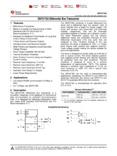
SN75176A Differential Bus Transceiver
www.ti.comVI or VIC Voltage at any buss terminal (separately or common mode) –7 12 V VIH High-level input voltage D, DE, and RE 2 V VIL Low-level input voltage D, DE, and RE 0.8 V VID Differential input voltage(1) ±12 V IOH High-level output current Driver –60 mA Receiver –400 µA IOL Low-level output current Driver 60 mA Receiver 8

MCP2551 High-Speed CAN Transceiver
ww1.microchip.comNov 07, 2016 · differential voltage between CANH and CANL is greater than a defined voltage (e.g.,1.2V). A Recessive state occurs when the differential voltage is less than a defined voltage (typically 0V). The Dominant and Recessive states correspond to the Low and High state of the TXD input pin, respectively. However, a

LM833 Dual High-Speed Audio Operational Amplifier ...
www.ti.com(2) All voltage values, except differential voltages, are with respect to the midpoint between VCC+ and VCC–. (3) The magnitude of the input voltage must never exceed the magnitude of the supply voltage. (4) Excessive input current will flow if a differential input voltage in excess of approximately 0.6 V is applied between the inputs, unless

PCA82C250 CAN controller interface
www.nxp.comVCC supply voltage 4.5 5.5 V ICC supply current Standby mode - 170 A 1/tbit maximum transmission speed non-return-to-zero 1 - MBd VCAN CANH, CANL input/output voltage 8+18V Vdiff differential bus voltage 1.5 3.0 V tPD propagation delay High-speed mode - 50 ns Tamb ambient temperature 40 +125 C