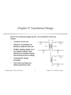
Chapter 15 Transformer Design
Fundamentals of Power Electronics Chapter 15: Transformer design11 15.2 Step-by-step transformer design procedure The following quantities are specified, using the units noted: Wire effective resistivity ( -cm) Total rms winding current, ref to pri Itot (A) Desired turns ratios n2/n1, n3/n1, etc. Applied pri volt-sec 1 (V-sec)
Download Chapter 15 Transformer Design

Information
Domain:
Source:
Link to this page:
Documents from same domain
Low-Power, Slew-Rate-Limited RS-485/RS-422 …
ecee.colorado.eduMAX481/MAX483/MAX485/MAX487–MAX491/MAX1487 Low-Power, Slew-Rate-Limited RS-485/RS-422 Transceivers ...

Assembly Language Programming Basics
ecee.colorado.edu1 © Copyright 2004 Linden H. McClure, Ph.D. 1 Assembly Language Programming Basics An introduction to microprocessor concepts, assembly language, and assembly processes

The Polyphase Induction Motor - University of …
ecee.colorado.eduThe Polyphase Induction Motor The polyphase induction motor is the ... armature or stator structure similar to that of the alternating current ... polyphase machine ...

Application Note 83 Fundamentals of RS–232 Serial ...
ecee.colorado.eduApplication Note 83 Fundamentals of RS–232 Serial Communications APPLICATION NOTE 83 030998 1/9 Due to it’s relative simplicity and …
DC-DC Power Converters - University of Colorado …
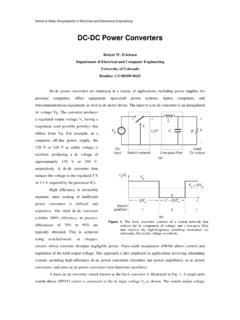
ecee.colorado.eduDC-DC Power Converters ... In practice, the SPDT switch is realized using semiconductor devices such as diodes, power MOSFETs, IGBTs, BJTs, or thyristors.

dB or not dB? Everything you ever wanted to know …
ecee.colorado.edudB or not dB? Everything you ever wanted to know about decibels but were afraid to ask . . . Application Note 1MA98 A. Winter, 05.2014 ... 1 Introduction %, dB, dBm and dB(µV/m) are important concepts that every engineer ... radio frequency engineering can be represented with more manageable numbers . Example: P

Table of Contents - University of Colorado Boulder
ecee.colorado.edu4 Introduction Preface Do we need another SPICE? Analog circuit simulation has been inseparable from analog IC design. SPICE simulators are the only way to check circuitry

Converter System Modeling via MATLAB/Simulink
ecee.colorado.eduConverter System Modeling via MATLAB/Simulink A powerful environment for system modeling and simulation MATLAB: programming and scripting environment Simulink: block diagram modeling environment that runs inside MATLAB Things we can achieve, relative to Spice:

Standard Resistor Values ( 5%) - ecee.colorado.edu
ecee.colorado.eduStandard Resistor Values ( ±5%) 1.0 10 100 1.0K 10K 100K 1.0M 1.1 11 110 1.1K 11K 110K 1.1M 1.2 12 120 1.2K 12K 120K 1.2M 1.3 13 130 1.3K 13K 130K 1.3M
How to Write a Technical Paper: Structure and …
ecee.colorado.eduHow to Write a Technical Paper: Structure and Style of the Epitome of your Research†‡ Georgios Varsamopoulos Department of Computer Science and Engineering
Related documents
Understanding Digital Signal Processing
ptgmedia.pearsoncmg.com9.3 Impulse Response of a Hilbert Transformer 487 9.4 Designing a Discrete Hilbert Transformer 489 9.5 Time-Domain Analytic Signal Generation 495 9.6 Comparing Analytical Signal Generation Methods 497 References 498 Chapter 9 Problems 499 10 SAMPLE RATE CONVERSION 507 10.1 Decimation 508 10.2 Two-Stage Decimation 510 10.3 Properties of ...
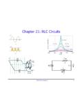
Chapter 21: RLC Circuits
www.phys.ufl.eduPHY2054: Chapter 21 29 Transformers: Sample Problem ÎA transformer has 330 primary turns and 1240 secondary turns. The input voltage is 120 V and the output current is 15.0 A. What is the output voltage and input current? 1240 120 451V 330 s sp p N VV N ⎛⎞ == =⎜⎟ ⎝⎠ “Step-up” transformer iV iV pp ss= 451 15 56.4A 120 s ps p V ...
Chapter 10 AC Inductor Design - coefs.uncc.edu
coefs.uncc.edudesign. Magnetic materials and their operating flux levels are given in Chapter 2. The ac inductor like a transformer, must support the applied voltage, Vac. The number of turns is calculated from Faraday's Law, which states: 10' P, [turns] [10-7] KfB,,cfAc The inductance of an iron-core inductor, with an air gap, may be expressed as:

Chapter 5
pages.mtu.eduBasic principles The transformer may be considered as a simple two-wheel 'gearbox' for electrical voltage and current. The primary winding is analogous to the input shaft The secondary winding is analogous to the output shaft. In this comparison, current is equivalent to shaft speed and voltage to shaft torque. In a gearbox, mechanical power (speed multiplied by torque) is …
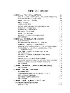
CHAPTER 3: SENSORS - Analog Devices
www.analog.comCHAPTER 3: SENSORS SECTION 3.1: POSITIONAL SENSORS Linear Variable Differential Transformers (LVDTs) The linear variable differential transformer (LVDT) is an accurate and reliable method for measuring linear distance. LVDTs find uses in modern machine-tool, robotics, avionics, and computerized manufacturing.

Chapter 5 Protection Circuit Design - Fuji Electric
www.fujielectric.comtransformer • Low detection precision • Arm short-circuit ... protective circuit built in, thereby simplifying the drive circuit design. For more details, refer to Chapter ... 1200V 50A 15 max. 22 min. - 0.47 75A 4.7 min. * Chapter 5 Protection Circuit Design .

Appendix 9C: Design Calculations for Electrical Design
www.seattle.govChapter 9 Electrical Design Appendix 9C Design Calculations for Electrical Design SPU Design Standards and Guidelines November 2020 5 5.2 DIRECT CURRENT (DC) FORMULAS Basic Formulas Volts V = I x R Power in watts P V I P I R = × = 2 × 5.3 ALTERNATING CURRENT (AC) SINGLE PHASE V denotes line to neutral voltage. Basic Formulas Volts V =I ×Z