
Chapter 5 Stresses in Beam (Basic Topics)
"c = "2 = C = - CCCCCCCC = - 89.8 MPa S2 40,100 thus ("t)max occurs at the section of maximum positive moment ("t)max = 50.5 MPa and ("c)max occurs at the section of maximum negative moment ("c)max = - 89.8 MPa 5.6 Design of Beams for Bending Stresses design a beam : type of construction, materials, loads and environmental conditions
Download Chapter 5 Stresses in Beam (Basic Topics)

Information
Domain:
Source:
Link to this page:
Documents from same domain

Chapter 9 Deflections of Beams - 首頁
ocw.nthu.edu.tw2 1 d = C = C ! ds the sign convention is pictured in figure slope of the deflection curve dv dv C = tan or = tan-1 C dx dx

LAPLACE TRANSFORM AND ITS APPLICATION IN …
ocw.nthu.edu.twC.T. Pan 1 LAPLACE TRANSFORM AND ITS APPLICATION IN CIRCUIT ANALYSIS C.T. Pan 2 12.1 Definition of the Laplace Transform 12.2 Useful Laplace Transform Pairs

RESPONSE OF FIRST-ORDER RC AND RL CIRCUITS
ocw.nthu.edu.twC.T. Pan 1 RESPONSE OF FIRST-ORDER RC AND RL CIRCUITS C.T. Pan 2 7.1 The Natural Response of an RC Circuit 7.2 The Natural Response of an RL Circuit

Chapter 7 Analysis of Stresses and Strains - 首頁
ocw.nthu.edu.twChapter 7 Analysis of Stresses and Strains 7.1 Introduction axial load " = P / A torsional load in circular shaft $ = T! / Ip bending moment and shear force in beam " = M y / I $ = V Q / I b in this chapter, we want to find the normal and shear stresses acting on ... the stress components for any orientation this is referred as stress ...

Chapter 3 Torsion - 首頁
ocw.nthu.edu.tw3 d& / dx represents the rate of change of the angle of twist &, denote = d& / dx as the angle of twist per unit length or the rate of twist, then max = r in general, & and are function of x, in the special case of pure torsion, is constant along the length (every cross section is subjected to the same torque)
Chapter 5 Stresses in Beam (Basic Topics) - 首頁
ocw.nthu.edu.tw3 5.4 Longitudinal Strains in Beams consider a portion ab of a beam in pure bending produced by a positive bending moment M, the cross section may be of any shape provided it is symmetric about y-axis under the moment M, its axis is bent into a circular curve, cross section mn and pq remain plane and normal to longitudinal lines (plane remains plane can be established by experimental result)
Chapter 3 Torsion
ocw.nthu.edu.tw3 d& / dx represents the rate of change of the angle of twist &, denote = d& / dx as the angle of twist per unit length or the rate of twist, then max = r in general, & and are function of x, in the special case of pure torsion, is constant along the length …
Chapter 9 Deflections of Beams
ocw.nthu.edu.twthe angle of rotation of the axis (also called slope) is the angle between the x axis and the tangent to the deflection curve point m1 is located at distance x ... = C = C = CC ! dx dx2 if the materials of the beam is linear elastic 1 M = C = C [chapter 5] ! EI then the differential equation of the deflection curve is obtained ...
Chapter 1 Tension, Compression, and Shear
ocw.nthu.edu.twstress-strain diagram of materials (compression test are most used for rock and concrete) cylindrical specimen are used ASTM standard specimen for tension test (round bar) d = 0.5 in (12.7 mm) GL = 2.0 in (50 mm) when the specimen is mounted on a testing system (MTS, Instron etc.), the load P and the elongation between GL are measured
LAPLACE TRANSFORM AND ITS APPLICATION IN CIRCUIT …
ocw.nthu.edu.twThe Laplace transform is an integral transformation of a function f(t) from the time domain into the complex frequency domain, F(s). C.T. Pan 6 12.1 Definition of the Laplace Transform [ ] 1 1 1 ()()1 2 Look-up table ,an easier way for circuit application ()() j st j LFsftFseds j ftFs − + − == ⇔ ∫sw psw One-sided (unilateral) Laplace ...
Related documents
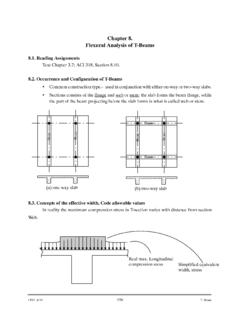
Chapter 8. Flexural Analysis of T-Beams - Memphis
www.ce.memphis.eduCIVL 4135 156 T--Beam Chapter 8. Flexural Analysis of T-Beams 8.1. Reading Assignments Text Chapter 3.7; ACI 318, Section 8.10. 8.2. Occurrence and Configuration of T-Beams • Commonconstructiontype.- usedinconjunctionwitheitheron-wayortwo-wayslabs. • Sections consists of the flange and web or stem; the slab forms the beam flange, while
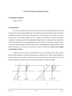
5. Flexural Analysis and Design of Beams 5.1. Reading ...
www.ce.memphis.eduFlexural Analysis and Design of Beams 5.1. Reading Assignment Chapter 3 of text 5.2. Introduction ... 5.8. Strain Limits Method for Analysis and Design (ACI 318). ... Example. Calculate Nominal Moment Capacity of a Beam for Fy = 60 ksi Á t =0.005 c d t =0.375

LATERALLY RESTRAINED BEAMS
www.steel-insdag.orgMar 21, 2000 · LATERALLY RESTRAINED BEAMS If a flexural member is progressively loaded, it deflects and the curvature of such bending varies along its length. Initially the beam is elastic throughout its length. Let us consider a small portion of the beam at a point A as shown in Fig.1 (a) where the curvature is ρ.

Chapter 2: Bars and Beams - University of Florida
mae.ufl.edubeams loaded only at its ends (elementary beam theory). So, the following function is used for a beam element: v=v(x)=β 1+ β 2x+ β 3x2+ β 4x 3 which is approximate for a beam element loaded along its length instead of just at its ends. (Use of a linear displacement function would lead to slope discontinuity at a common node of two beam ...

CHAP 4 FINITE ELEMENT ANALYSIS OF BEAMS AND FRAMES
mae.ufl.edu1 CHAP 4 FINITE ELEMENT ANALYSIS OF BEAMS AND FRAMES 2 INTRODUCTION • We learned Direct Stiffness Method in Chapter 2 – Limited to simple elements such as 1D bars • we will learn Energy Methodto build beam finite element – Structure is in equilibrium when the potential energy is minimum
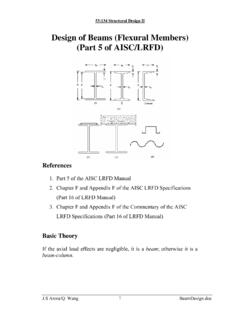
Design of Beams (Flexural Members) (Part 5 of AISC/LRFD)
user.engineering.uiowa.edu53:134 Structural Design II My = the maximum moment that brings the beam to the point of yielding For plastic analysis, the bending stress everywhere in the section is Fy , the plastic moment is a F Z A M F p y ⎟ = y 2 Mp = plastic moment A = total cross-sectional area a = distance between the resultant tension and compression forces on the cross-section a A
ACI 318-14 - American Concrete Institute
www.concrete.org6.8—Inelastic second‐order analysis 6.8.1—General 6.9—Acceptability of finite element analysis Chapter 7—One‐Way Slabs 7.1—Scope 7.1.1—This chapter shall apply to the design of nonprestressed and prestressed slabs reinforced for flexure in …

Structural Analysis Equations - Forest Products Laboratory
www.fpl.fs.fed.usbeam depth h0 can be calculated for comparison with that given by the design criteria. Conversely, the deflection of a beam can be calculated if the value of the abscissa is known. Tapered beams deflect as a result of shear deflection in ad-dition to bending deflections (Figs. 9–1 and 9–2), and this