Example: tourism industry
Structural Analysis Equations - Forest Products Laboratory
beam depth h0 can be calculated for comparison with that given by the design criteria. Conversely, the deflection of a beam can be calculated if the value of the abscissa is known. Tapered beams deflect as a result of shear deflection in ad-dition to bending deflections (Figs. 9–1 and 9–2), and this
Tags:
Information
Domain:
Source:
Link to this page:
Documents from same domain

Wood Handbook--Chapter 4--Mechanical Properties of Wood
www.fpl.fs.fed.us4–1 Chapter 4 Mechanical Properties of Wood David W. Green, Jerrold E. Winandy, and David E. Kretschmann Contents Orthotropic Nature of Wood 4–1
Wood Handbook--Chapter 9--Adhesive Bonding of Wood …
www.fpl.fs.fed.usChapter 9 Adhesive Bonding of Wood Materials Charles B. Vick Contents Adhesion to Wood 9–1 Surface Properties of Wood Adherends 9–2 Extractives on Surfaces 9–3 ... though covalent chemical bonds between adhesive polymer and the molecular structure of wood seem a possibility, there

Wood Handbook, Chapter 11: Mechanical Properties of …
www.fpl.fs.fed.us12–3 Chapter 12 Mechanical Properties of Wood-Based Composite Materials ASTM D 7031 for wood–plastic composites, and ASTM D 7341 for glulam products.
CHAPTER 8 FIRE - Forest Products Laboratory
www.fpl.fs.fed.us2012 CLT Handbook (US Edition) – Chapter 8: Fire Nov. 29,2012 Cross-laminated timber (CLT) is a promising wood-based structural component and has potential to provide cost-effective building solutions for residential, commercial and institutional buildings
Profile extrusion and mechanical properties of …
www.fpl.fs.fed.usProfile Extrusion and Mechanical Properties of Crosslinked Wood–Thermoplastic Composites ... Struktol TMW113 was ob-tained from Struktol Company of America ...
Co-Extrusion of WPCs with a Clear Cap Layer to …
www.fpl.fs.fed.usCo-Extrusion of WPCs with a Clear Cap Layer to Improve Color Stability ... Struktol Company of America (Stow, OH) TR 065 :
STRENGTH OF SINGLE-POLE UTILITY STRUCTURES …
www.fpl.fs.fed.uscan be achieved across material types by setting nominal resistance values that represent a 5% to 10% lower exclusion limit (LEL) equal to the design ... 1990]; PCI 1999]). The organizations that set these standards provide for ... STRENGTH OF SINGLE-POLE UTILITY STRUCTURES .
Discoloration of House Paint - Causes and Cures
www.fpl.fs.fed.usDiscoloration of House Paint –Causes and Cures Daniel L. Cassens, Department of Forestry and Natural Resources, Purdue University, and ... Use a vapor barrier on the interior side of ail exterior walls to prevent condensation in the wall. Vent clothes dryers, showers and cooking areas to the outside, and avoid theuse of humidifiers. Untreated
Fire Resistance of Exposed Wood Members
www.fpl.fs.fed.us338 WOOD & FIRE SAFETY CALCULATION PROCEDURES For an exposed wood member, the fire resistance rating is the time for structural failure when subjected to the standard fire exposure.
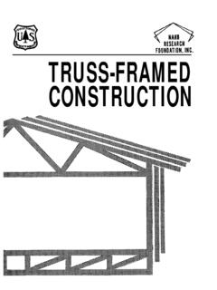
Truss-framed Construction
www.fpl.fs.fed.usThe Truss-Framed System (TFS) described in this manual is an innovative wood-framed construction method developed by the Forest
Related documents
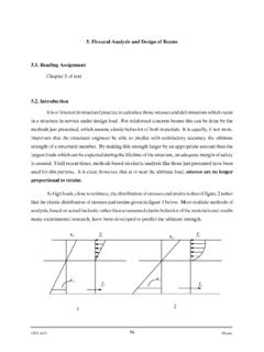
5. Flexural Analysis and Design of Beams 5.1. Reading ...
www.ce.memphis.eduFlexural Analysis and Design of Beams 5.1. Reading Assignment Chapter 3 of text 5.2. Introduction ... 5.8. Strain Limits Method for Analysis and Design (ACI 318). ... Example. Calculate Nominal Moment Capacity of a Beam for Fy = 60 ksi Á t =0.005 c d t =0.375
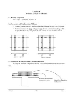
Chapter 8. Flexural Analysis of T-Beams - Memphis
www.ce.memphis.eduCIVL 4135 156 T--Beam Chapter 8. Flexural Analysis of T-Beams 8.1. Reading Assignments Text Chapter 3.7; ACI 318, Section 8.10. 8.2. Occurrence and Configuration of T-Beams • Commonconstructiontype.- usedinconjunctionwitheitheron-wayortwo-wayslabs. • Sections consists of the flange and web or stem; the slab forms the beam flange, while

CHAP 4 FINITE ELEMENT ANALYSIS OF BEAMS AND FRAMES
mae.ufl.edu1 CHAP 4 FINITE ELEMENT ANALYSIS OF BEAMS AND FRAMES 2 INTRODUCTION • We learned Direct Stiffness Method in Chapter 2 – Limited to simple elements such as 1D bars • we will learn Energy Methodto build beam finite element – Structure is in equilibrium when the potential energy is minimum
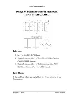
Design of Beams (Flexural Members) (Part 5 of AISC/LRFD)
user.engineering.uiowa.edu53:134 Structural Design II My = the maximum moment that brings the beam to the point of yielding For plastic analysis, the bending stress everywhere in the section is Fy , the plastic moment is a F Z A M F p y ⎟ = y 2 Mp = plastic moment A = total cross-sectional area a = distance between the resultant tension and compression forces on the cross-section a A

LATERALLY RESTRAINED BEAMS
www.steel-insdag.orgMar 21, 2000 · LATERALLY RESTRAINED BEAMS If a flexural member is progressively loaded, it deflects and the curvature of such bending varies along its length. Initially the beam is elastic throughout its length. Let us consider a small portion of the beam at a point A as shown in Fig.1 (a) where the curvature is ρ.

Chapter 2: Bars and Beams - University of Florida
mae.ufl.edubeams loaded only at its ends (elementary beam theory). So, the following function is used for a beam element: v=v(x)=β 1+ β 2x+ β 3x2+ β 4x 3 which is approximate for a beam element loaded along its length instead of just at its ends. (Use of a linear displacement function would lead to slope discontinuity at a common node of two beam ...

Chapter 5 Stresses in Beam (Basic Topics)
ocw.nthu.edu.tw"c = "2 = C = - CCCCCCCC = - 89.8 MPa S2 40,100 thus ("t)max occurs at the section of maximum positive moment ("t)max = 50.5 MPa and ("c)max occurs at the section of maximum negative moment ("c)max = - 89.8 MPa 5.6 Design of Beams for Bending Stresses design a beam : type of construction, materials, loads and environmental conditions
ACI 318-14 - American Concrete Institute
www.concrete.org6.8—Inelastic second‐order analysis 6.8.1—General 6.9—Acceptability of finite element analysis Chapter 7—One‐Way Slabs 7.1—Scope 7.1.1—This chapter shall apply to the design of nonprestressed and prestressed slabs reinforced for flexure in …