CHARGING SYSTEMS
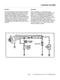
suspected. Output current and voltage should meet the specifications of the alternator. If not, the alternator or regulator (IC or external) may require replacement. A Sun VAT-40 tester, similar testers, or a separate voltmeter and ammeter can be used. Toyota repair manuals detail the testing procedures with an ammeter and voltmeter.
Download CHARGING SYSTEMS

Information
Domain:
Source:
Link to this page:
Documents from same domain
GENERAL MOTORS - Autoshop 101
www.autoshop101.comBODY ELECTRICAL GENERAL MOTORS PRACTICE ELECTRICAL WIRING DIAGRAMS http://www.autoshop101.com Compiled by Kevin R. Sullivan CLASSROOM PRACTICE SHEETS
TOYOTA ELECTRONIC TRANSMISSION CHECKS & …
www.autoshop101.comDiagnosis During diagnosis, always verify the customer complaint. If the verification includes a test drive, be sure to check the level of ATF first.
ANALOG AND DIGITAL METERS - Autoshop 101
www.autoshop101.comANALOG VS. DIGITAL METERS Ultimately, your diagnosis of vehicle electrical system problems will come down to using a voltmeter, ammeter, or ohmmeter to …
BATTERY SERVICE - Autoshop 101
www.autoshop101.comPage 1 © Autoshop101.com. All rights reserved. BATTERY SERVICE This Automotive Series BATTERY SERVICE has been developed by Kevin R. Sullivan
Section 2 Using the Electrical Wiring Diagram
www.autoshop101.comUsing the Electrical Wiring Diagram Body Electrical Diagnosis - Course L652 3 One of the keys to a quick and successful electrical diagnosis is correctly
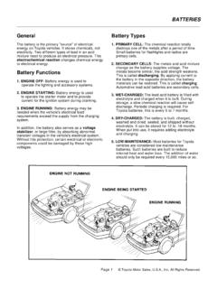
General Battery Types - Automotive Training and …
www.autoshop101.comGeneral The battery is the primary "source" of electrical energy on Toyota vehicles. It stores chemicals, not electricity. Two different types of lead in an acid
Section 1 Essential Electrical Concepts
www.autoshop101.comSection 1 1-2 TOYOTA Technical Training Different meters are used to measure voltage, current, and resistance: •Voltmeter - to measure voltage •Ammeter - to measure current
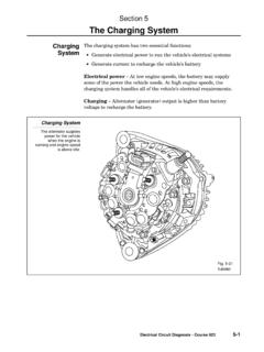
Section 5 The Charging System
www.autoshop101.comThe Charging System Electrical Circuit Diagnosis - Course 623 5-3 The alternator contains these main components: •Stator (attached to …
SENSORS AND ACTUATORS - Autoshop 101
www.autoshop101.comSENSORS AND ACTUATORS Computer controlled systems continually monitor the operating condition of today's vehicles. Through sensors, computers receive vital information about a number of
ELECTRICAL CIRCUITS Electrical Circuits - Autoshop …
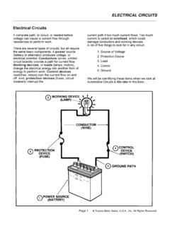
www.autoshop101.comElectrical Circuits A complete path, or circuit, is needed before voltage can cause a current flow through resistances to perform work. …
Related documents
Understanding Non Contact Voltage Testers
www.homeinspect2020.comvoltage tester. Amprobe TIC 300 “Voltage Proximity Testers are a relatively simple testing instrument that enables electricians and other uses to locate, trace and identify common electrical problems. These testers can locate wires behind walls, underground, ... Continuity checks test a …

Photovoltaic System Commissioning and Testing
www.mavetech.net5.1 Continuity Testing 20 5.2 Polarity Testing 23 5.3 Voltage and Current Testing 24 5.3.1 Open-Circuit Voltage Testing 25 5.3.2 Short-Circuit Current Testing 25 5.4 Insulation Resistance Testing 26 5.5 System Functional Testing 29 5.5.1 Test Reports 30 6 System Performance Testing 30 6.1 Verifying Power and Energy Production 30
Section 5 The Charging System - Autoshop 101
www.autoshop101.com1. Keep the tester connections as for the alternator output test with no load. 2. Adjust engine speed to specified RPM (refer to the appropriate service manual). 3. Adjust the tester’s load control to obtain the highest ammeter reading possible while keeping the voltage reading at or above 12 volts. 4. Record the highest ammeter reading.

TESTING FOR VOLTAGE DROP
drivcat.comcannot reliably be obtained through the use of continuity testing with an Ohmmeter. Multi-strand wires may test properly for continuity, but due to opens or corrosion in the line, display a substantial voltage drop when tested. Voltage Drop testing is a method of electrical diagnosis that can quickly locate high-resistance problems in a circuit.
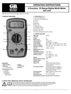
OPERATING INSTRUCTIONS 4 Function, 15 Range Digital …
file.ecmindustries.comWith DC voltage, the polarity of the test leads is a factor. ... Typical resistance/continuity measurements include resistors, potentiometer, switches, extension cords and fuses. ... Remove the screws in the back cover of the tester and carefully separate the back cover from the front. 3. Remove the battery from the contacts, noting the ...

WF-8900 Series
wfcoelectronics.comvoltage is changed back to 13.6 VDC for Absorption Mode. Lights that are powered from the output may change brightness slightly at that time. ... use a continuity tester to check for continuity. If the reverse polarity fuses are blown, it means the RV battery was accidentally connected in reverse, either at the battery or at the converter ...

ELECTRONIC PLAYGROUND TM - Elenco
www.elenco.comChanging Input Voltage 90 72. Non-inverting Dual Supply Op Amp 91 73. Inverting Dual Supply Op Amp 92 74. Non-inverting Amplifier 93 ... Audio Continuity Tester 143 122. Audio Rain Detector 144 123. Audio Metal Detector 145 124. Water Level Buzzer 146 ...
IDEAL INDUSTRIES INC.
www.idealind.comVoltage, current and resistance are the three most fundamental components of electricity. Voltage is measured in volts, current in amps and resistance in ohms. . Voltage, Current and Resistance Voltage is the pressure that is applied to a conductor. There are two common types of power sources, Alternating Current (AC) and Direct Current (DC).
Electrical Safety Testing Reference Guide
www.psma.comFeb 28, 2001 · S 10/15 AC Hipot Tester 37 S 20/25 AC/DC Hipot Tester 37 S 30/35 AC/DC/IR Hipot Tester 37 S50 Ground Bond Tester 37 Guardian Series Testers 38 Common Features 38 Guardian 1000 Series G 1010 AC Hipot Tester 38 G 1030 AC/DC/IR Hipot Tester 38 G 1030S AC/DC/IR/SC Hipot Tester 38 Guardian 2000 Series G 2510 AC Hipot Tester 38

ELECTRICIAN
www.rrbbnc.gov.involtage, current, resistance, power, power factor and energy using ammeter, voltmeter, ohm-meter, watt-meter, energy meter, power factor meter and phase sequence tester with proper care and safety. 12. Make choices to carry out basic jobs …