
Cross sectional Shape Selection
ME 474-674 Winter 2008 Slides 9 -5 Elastic Bending I = Moment of inertia of the cross section Table 11.2 gives the section properties of different shapes For a circular cross section If S is the stiffness for another shape with the same cross sectional area made of the same material and subject to the same loading, then the shape factor for elastic bending is defined as
Download Cross sectional Shape Selection

Information
Domain:
Source:
Link to this page:
Documents from same domain
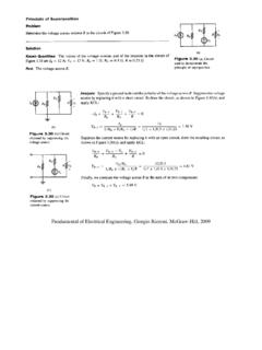
Fundamental of Electrical Engineering, Giorgio …
cecs.wright.eduFundamental of Electrical Engineering, Giorgio Rizzoni, McGraw-Hill, 2009 . Ideal Transformer Relations (Equations) Definitions: Primary Winding (input - subscript 1)

ME 2120: STATICS, MID-TERM EXAM 1 Open Book, …
cecs.wright.eduME 2120: STATICS, MID-TERM EXAM 1 Open Book, Closed Notes, Show All Work for Partial Credit All Results Must Show at Least Three Significant Digits Problem 1: (8 points) A hoist trolley is subjected to the three forces shown. Knowing that

HEAT CONDUCTION EQUATION H - Wright State University
cecs.wright.eduHEAT CONDUCTION EQUATION H eat transfer has direction as well as magnitude. The rate of heat conduc-tion in a specified direction is proportional to the temperature gradient, which is the rate of change in temperature with distance in that direction.

BJT Bias Homework Problems 1-5 - Wright State University
cecs.wright.eduBJT Biasing Homework Problems 3. Voltage-Divider Biased, Common Emitter Configuration Calculate the quiescent points (I CQ and V CEQ) And determine V CE Cut-off and I C Saturation β = 100 V CC = 16 V R 1 = 47K Ω R 2 = 12K Ω R C = 2200 Ω R E = 1800 Ω Find: a. Quiescent Current I CQ b. Quiescent Voltage V CEQ c. V CE Cut-off d. I C Saturation 4.

PROPERTY TABLES AND CHARTS (SI UNITS)
cecs.wright.eduPROPERTY TABLES AND CHARTS (SI UNITS) TABLE A–1 Molar mass, gas constant, and ideal-gas specific heats of some substances 866 TABLE A–2 Boiling and freezing point properties 867 TABLE A–3 Properties of solid metals 868–870 TABLE A–4 Properties of solid nonmetals 871 TABLE A–5 Properties of building materials 872–873 TABLE A–6 Properties of insulating …
Related documents
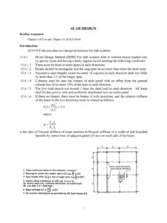
SLAB DESIGN - Memphis
www.ce.memphis.edu5. Design beams if any, using procedures you learned in CIVL 4135. Positive and Negative Distribution of Moments For interior spans, the total static moment is apportioned between critical positive and negative bending sections as (See ACI 318-02 Sect. 13.6.3): Panel Moment Mo 100% Static Moment Negative Moment Mo negative Mu = 0.65 Mo Positive ...
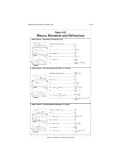
BEAM DIAGRAMS AND FORMULAS
www-classes.usc.edu3-216 DESIGN OF FLEXURAL MEMBERS Table 3-23 {continued) Shears, Moments and Deflections 10. SIMPLE BEAM-TWO EQUAL CONCENTRATED LOADS UNSYMMETRICALLY PLACED
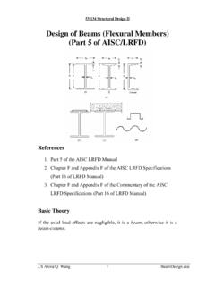
Design of Beams (Flexural Members) (Part 5 of AISC/LRFD)
user.engineering.uiowa.edu53:134 Structural Design II My = the maximum moment that brings the beam to the point of yielding For plastic analysis, the bending stress everywhere in the section is Fy , the plastic moment is a F Z A M F p y ⎟ = y 2 Mp = plastic moment A = total cross-sectional area a = distance between the resultant tension and compression forces on the cross-section a A
BEAM-COLUMNS
www.labciv.eng.uerj.br• The interaction of normal force and bending may be treated elastically or plastically using equilibrium for the classification of cross-section. • The behaviour and design of beam-columns are presented within the context of members subjected to uniaxial bending, i.e. deformation takes place only in the plane of the applied moments.

Chapter 2. Design of Beams – Flexure and Shear
www.egr.msu.eduCE 405: Design of Steel Structures – Prof. Dr. A. Varma • In Figure 4, My is the moment corresponding to first yield and Mp is the plastic moment capacity of the cross-section. - The ratio of Mp to My is called as the shape factor f for the section. - For a rectangular section, f is equal to 1.5. For a wide-flange section, f is equal to 1.1. ...

BEAM DESIGN FORMULAS WITH SHEAR AND MOMENT
engineering.purdue.eduJan 06, 2005 · Shear and moment diagrams and formulas are excerpted from the Western Woods Use Book, 4th edition, and are provided herein as a courtesy of Western Wood Products Association. Introduction Notations Relative to “Shear and Moment Diagrams” E = modulus of elasticity, psi I = moment of inertia, in.4 L = span length of the bending member, ft.

R.C.C WATER TANKS
www.gn.dronacharya.info3)DESIGN OF BASE SLAB:- Specification Size Reinforcement details Base slab Short span I. -ve bending moment II. +ve bending moment Long span I. -ve bending moment II. +ve bending moment 5m×4m 16mm Ø @80mm c/c 16mm Ø @110mm c/c 16mm Ø @110mm c/c 10mm Ø @220mm c/c 30

Combined Bending and Axial Loads
user.engineering.uiowa.edubending moment Mu have been recognized as the practical procedure for design. • Axial compression strength requirement Required axial strength ≤ Design axial strength of the section u c n ≤φP P, or 1 u cn P φP ≤ • Bending moment strength requirement Required bending strength ≤ Design bending strength of the section u b n ≤φM M ...

Design of Composite Beams with Large weB openings
www.steelconstruction.infodesign bending moment at the centreline of an opening bending resistance of the composite section at the centreline of an opening plastic bending resistance (of Tee section) bending resistance of the top Tee, reduced for axial tension and shear design bending moment in