
DC Electrical Circuit Analysis - MVCC
Subsequent chapters introduce resistance, series circuits, parallel circuits and series-parallel circuits. The text continues with chapters covering network theorems, more advanced techniques such as nodal and mesh analysis, and finally finishes with introductions to capacitors, inductors and magnetic circuits. The companion AC
Download DC Electrical Circuit Analysis - MVCC

Information
Domain:
Source:
Link to this page:
Documents from same domain
Laboratory Manual for Semiconductor Devices
www2.mvcc.eduEmbedded Controllers Using C and Arduino, and Science of Sound. OER texts for DC and AC Electrical Circuit Analysis, Embedded Controllers, and Operational Amplifiers & Linear Integrated Circuits are also available. Finally, this work supersedes the earlier “Laboratory Manual for Linear Electronics”. A Note from the Author
AC Electrical Circuit Analysis - MVCC
www2.mvcc.eduin a circuit, as well as between currents or resistive/reactive values. Many of the topics in this text will echo your studies in DC circuit analysis, such as Ohm's law, Kirchhoff's voltage and current laws, series-parallel analysis, nodal analysis, and the like. Thus many concepts will be familiar.

2 Laboratory Manual for Linear Electronics
www2.mvcc.edu4 Laboratory Manual for Linear Electronics This Laboratory Manual for Linear Electronics, by James M. Fiore is copyrighted under the terms of a Creative Commons license: This work is freely redistributable for non-commercial use, share-alike with attribution
Laboratory Manual for Computer Programming with …
www2.mvcc.eduThis laboratory manual is intended for use in an introductory computer programming course for electrical engineering technology students. It begins with a basic explanation of schematic capture and simulation tools and proceeds to the Python programming language. Python (version 3.X) was chosen for several reasons.

Digital Electronics 1 (ET181) Laboratory Manual
www2.mvcc.eduMar 21, 2018 · • Knight electronics ML-2001 logic trainer • Digital multimeter (DMM) • Logic probe Discussion: The digital logic trainer used in this lab includes a number of features to support the design and fabrication of logic circuits in the lab. The main features include: • Fixed and variable positive and negative DC power supplies
Related documents
Chapter 8 Natural and Step Responses of RLC Circuits
www.ee.nthu.edu.twChapter 8 Natural and Step Responses of RLC Circuits 8.1-2 The Natural Response of a Parallel RLC Circuit. 8.3 The Step Response of a Parallel . RLC . Circuit. 8.4 The Natural and Step Response of a Series . RLC . Circuit

DESIGNING COMBINATIONAL LOGIC GATES IN CMOS
bwrcs.eecs.berkeley.eduIn Figure 6.6b, the subnets (SN) for the pull-down etwork aren identified t the topA level, SN1 and SN2 are in parallel so in the dual network, they will be in series. Since SN1 B A A B Parallel Combination Figure 6.4 NMOS logic ules r — series devices implement an AND, and parallel devices implement an OR. (a) series (b) parallel Series ...
Chapter 12 Alternating-Current Circuits
web.mit.eduFigure 12.2.2 (a) Time dependence of IR (t) and VR (t) across the resistor.(b) Phasor diagram for the resistive circuit. The behavior of IR (t)and can also be represented with a phasor diagram, as shown in Figure 12.2.2(b). A phasor is a rotating vector having the following properties:

Chapter 6: Inductance and Capacitance
courses.egr.uh.eduChapter 6: Inductance and Capacitance We introduce here the two remaining basic circuit elements: the inductor and the capacitor. The behavior of the inductor is based on the properties of the magnetic field generated in a coil of wire. In fact, the inductor is basically a coil of wire. Ampere’s Law: current in a coil magnetic field

A TEXTBOOK OF ELECTRICAL TECHNOLOGY
elbook.weebly.com6. The chapter on Series A.C. Circuits has been enriched with many articles such as Determination of Upper and Lower Half-power Frequencies, Value of Edge Frequencies and Relation between Resonant Power and Off-resonance Power. ... Between Series and Parallel Circuits—Relative Potential— ...
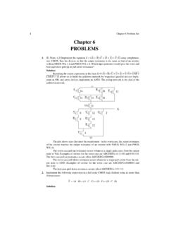
Chapter 6 PROBLEMS - #hayalinikeşfet
home.ku.edu.trThen, each of the pMOS has an output resistance equal to 6.5 k. The output resistance is equal to the series of one of these resistance with the parallel of four of the same resistnaces. Then, the minimum output resistance is 6.5 k + 6.5 k/4 = 8.125 k. 6. [E, None, 4.2] What is the logic function of circuits A and B in Figure 6.5? Which one is a
Chapter 18 Two-Port Circuits
www.ee.nthu.edu.tw1. Chapter 18 Two-Port Circuits. 18.1 The Terminal Equations. 18.2 The Two-Port Parameters. 18.3 Analysis of the Terminated Two-Port Circuit . 18.4 Interconnected Two-Port Circuits

Series -Parallel Circuits
www.oakton.edu6-1: Finding RTfor Series -Parallel Resistances Overview of Series-Parallel Circuits A series-parallel circuit, or combination circuit, combines both series and parallel connections. Most electronic circuits fall into this category. Series-parallel circuits are typically used when different voltage and current values are required from the same

Electric circuits, Current, and resistance (Chapter 22 and 23)
www.physics.brocku.catraded for a 6.0 V battery. The power dissipated by the resistoris now A. 1.0 W B. 2.0 W C. 3.0 W D. 4.0 W Multiple choice Problem 1: An electric blanket has a wire that runs through the interior. A current causes energy to be dissipated in the wire, warming the blanket. A new, low-voltage electric blanket is rated to be used at 18 V.