
DIAGNOSTIC FLOW CHART FOR E-46, E-47 and E-57 …
DIAGNOSTIC FLOW CHART FOR E-46, E-47 and E-57 ELECTRO LIFT® UNITS These charts are intended to be used as an aid in diagnosing problems on the …
Download DIAGNOSTIC FLOW CHART FOR E-46, E-47 and E-57 …

Information
Domain:
Source:
Link to this page:
Documents from same domain

CLICK ON ADAPTOR PART NUMBER - Meyer Products
ww2.meyerproducts.comCLICK ON ADAPTOR PART NUMBER SABER HEADLIGHTS ADAPTER CROSS REFERENCE DRL go through Truck Lights. Replacement Bulb Chevy/GMC Vehicles New Body Style

E-72 power unit service manual - Meyer Products
ww2.meyerproducts.comfunctions in the same manner. The pump pressure relief valve may be adjusted to the specified pressure of 2000 P.S.I. by adjusting the set screw after installing a suitable pressure gauge of 2500 P.S.I. in the circuit. SOLENOID VALVES Hydraulic valves are simple in concept and all have the same basic function: Control the direction of oil flow.

E-58H power unit service manual - Meyer Products
ww2.meyerproducts.comin the same manner. The pump pressure relief valve may be adjusted to the specified pressure of 2000 P.S.I. by adjusting the set screw after installing a suitable pressure gauge of 2500 P.S.I. in the circuit. SOLENOID VALVES Hydraulic valves are simple in concept and all have the same basic function: Control the direction of oil flow.

ELECTRO LIFT power units service manual
ww2.meyerproducts.comshown in Figure 0-1. The serial number is located on the bottom of the base or on the name plate. Motor Identification Three different brand motors are used on the Electro Lift® units American Bosch, Prestolite and Iskra. Proper identification of the brand and supplier part number is necessary when seeking local parts and service sources.
DIAGNOSTIC FLOW CHART FOR E-46, E-47 and E-57 …
ww2.meyerproducts.comDIAGNOSTIC FLOW CHART FOR E-46, E-47 and E-57 ELECTRO LIFT® UNITS These charts are intended to be used as an aid in diagnosing problems on the Electro Lift® units. They are not a substitute for factory training and experience. Be certain to read the General Information and Testing Tips sections before attempting any trouble-shooting. General ...

PARTS & INSTALLATION INSTRUCTIONS E-46 & E-47 …
ww2.meyerproducts.coma) The damaged pump drive Shaft Seal (3) may be removed by careful extraction with a pointed tool. Dip new Seal in oil and with lip down, press into Pump Housing flush to 1/32 inch below face of boss. 4. BASE (24) a) Remove and clean Solenoid (40) and inspect for external damage. b) Test Coil (41) for electrical continuity. Nominal Coil

PARTS & INSTALLATION INSTRUCTIONS E-47 & E-47H …
ww2.meyerproducts.comAmp. Hr. Min.) 550 C.C.A. and "Alternator" (60 amp. Min.) to obtain maximum performance. 5. Follow these instructions explicitly. Warranty does not apply to a Meyer product which has been negligently or improperly assembled or installed. PARTS & INSTALLATION INSTRUCTIONS E-47 & E-47H MEYER ELECTRO TOUCH™ PARTS LIST
QUIK-LIFT power unit service manual - Meyer Products
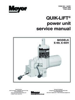
ww2.meyerproducts.comFOREWARD This Service Manual includes complete information for servicing the following Quik- Lift® E - 60, E - 60H Units: The information is grouped according to the type of work being performed, such as diagnosis and testing, disassembly
Related documents
ANALYSIS AND DESIGN OF LIQUID-COOLING SYSTEMS …
inres.com2 Copyright © 2003 by ASME ANALYSIS USING FLOW NETWORK MODELING The details of the FNM technique have been described in the earlier articles (Belady et al. [1]).
Fluorochrome/Laser Reference Poster - BD Biosciences
www.bdbiosciences.comFor Research Use Only. Not for use in diagnostic or therapeutic procedures. APC-Cy7: US patent 5,714,386 Cy™ is a trademark of GE Healthcare. Cy dyes are subject to ...
OBD II Inspection Flow Charts - Welcome to Drive Clean PA!
www.drivecleanpa.state.pa.usOBD II Inspection Flow Charts The flow charts are designed to help guide you through different inspection results you may encounter during the normal course of OBD II inspections and repairs.
Manual Refrigerator Diagnostic Service Manual - Serro Scotty
www.nationalserroscotty.orgMANUAL REFRIGERATOR DIAGNOSTIC FLOW CHART. NO OPERATION A. 1. Check Supply Voltage 1. 110 Volt Plug 2. Wire Size I~>1 Correct as Necessary. OK. B. V. Check Fuse

Dementia Post Diagnostic Support HEAT Target - QI Hub
www.qihub.scot.nhs.ukID: A5110749 Version: 5 Page 1 of 11 Dementia Post Diagnostic Support HEAT Target Information Flow Mapping Guide February 2013 DRAFT QuEST Quality and Efficiency Support Team
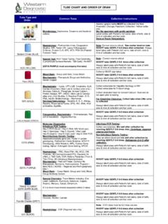
TUBE CHART AND ORDER OF DRAW - Western Diagnostic …
www.wdp.com.auTUBE CHART AND ORDER OF DRAW Tube Type and Order Common Tests Collection Instructions Blood Cultures Microbiology: Septicemia, Toxaemia and bacterial culture. Aerobic (green) bottle MUST be collected first then Anaerobic (Orange).Paediatric Collection- Yellow bottle
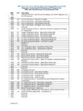
CNH ECU T3 T4 FC Cross Chart Dealer Version
www.eagrotec.czCNH ECU Tier 3 and Tier 4a Fault Code Cross Reference Chart Diagnostic Trouble Code (DTC) References FPT Engine Code CNH Fault Code References Vehicle Displayed Code

DIAGNOSTIC SERVICE MANUAL - fourwh.com
www.fourwh.com2 Page no. dIagnoStIc floW cHart..... 4 contentS SectIon 1 oPeratIon Refrigerator Operation .....6 SectIon 2