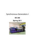
EE 340 Spring 2011 - UNLV
The rotor of a synchronous machine is a large electromagnet. The magnetic poles can be either salient (sticking out of rotor surface) or non- ... • It is possible to adjust the field current on the main machine by controlling the small DC field current …
Download EE 340 Spring 2011 - UNLV

Information
Domain:
Source:
Link to this page:
Documents from same domain

Power Semiconductor Switching Devices
www.egr.unlv.eduClassification of power semiconductor switches ... • The MCT is a power switch with a MOS gate for turn- on and turn-off. It

Power Semiconductor Switching Devices - …
www.egr.unlv.eduIdeal controllable Power Semiconductor Switch • When turned on, current can flow only in the direction of the arrow
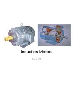
Induction Machines - Howard R. Hughes College of …
www.egr.unlv.edu3-Phase induction machine construction • 3 stator windings (uniformly distributed as in a synchronous generator) • Two types of rotor: – Squirrel cage
EE 340 – Transmission Lines
www.egr.unlv.eduElectrical Characteristics • Transmission lines are characterized by a series resistance, inductance, and shunt capacitance per unit length. • These values determine the power-carrying capacity of the

Mechanics of Materials - University of Nevada, Las Vegas
www.egr.unlv.eduME 302 Materials Mechanics Introduction and Overview This is a fundamental course in all Civil and Mechanical Engineering Programs. Sometimes it is called:

Resonant Converters - University of Nevada, Las Vegas
www.egr.unlv.edu9-12 ZCS Resonant-Switch Converter By controlling the switch-off time (t 4 - t 3), i.e., the switching frequency, the average value of v oi, hence the average power supplied to the load

PowerPoint Presentation
www.egr.unlv.eduThe Laplace Transform Theorem: Initial Value If the function f(t) and its first derivative are Laplace transformable and f(t) Has the Laplace transform F(s), and the exists, then

Sunlight and its Properties - Howard R. Hughes College of ...
www.egr.unlv.eduTypes of Radiations • Scattered sunlight (what makes the sky blue) is responsible for the light entering the north-facing windows. It is referred to as diffuse radiation.
Magnetic Circuits - UNLV
www.egr.unlv.eduAmpère in 1826) relates the integrated magnetic field around a closed loop to the electric current passing through the loop. where H is the magnetic field intensity (measured in At/m) • At a distance r from the wire, ³ H .dl I ³ H .dl H .( 2Sr ) I
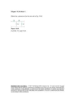
Obtain the z parameters for the network in Fig. 19.65.
www.egr.unlv.edu* Find the impedance parameter equivalent of the network in Fig. 19.66. Figure 19.66 For Prob. 19.2. * An asterisk indicates a challenging problem. Chapter 19, Solution 2. Consider the circuit in Fig. (a) to get z11 and z21. 1 Ω I2 = 0 + V1 − 1 Ω I1 (a) Io + V2 − Io' 1 Ω 1 Ω 1 Ω 1 Ω 1 Ω 1 Ω
Related documents

Synchronous Machines - Virginia Tech
www.courses.ece.vt.educurve (OCC) and the short-circuit current curve (SCC) for a typical machine. The voltage curve slope begins to decrease as the field current increases due to saturation of the iron in the machine. Figure 12: Open-circuit and short-circuit characteristics of a synchronous machine at rated speed. The impedance is Z = R jX s 1

Sensorless Field Oriented Control (FOC) for Permanent ...
www.microchip.com2. PMSM motors are also becoming popular in Direct Drive washing machine due to their torque available at very low speeds. FOC enables better dynamic response in a washing machine without increasing the overall system cost. 3. Refrigerator compressors also require better efficiency and torque performance at low speeds.
Permanent Magnet Synchronous Machine Model for Real
web.mit.educircuit of the machine will be the circuit shown in Fig. 4. Rmmi ω0Ψq Rm d Lmd d dt Ψ + − + − Vd id if d f dt Ψ + − Rs ls Fig. 4. D axis thevenin equivalent circuit of the PMSM This model is similar to the conventional equivalent circuit of the synchronous machine, except there is no leakage inductance on the field. C. Typical data ...

III. Synchronous Motors - University of Technology, Iraq
www.uotechnology.edu.iqSuppose the synchronous motor is initially overexcited (in other words, excited with a large field current) and is operating at point , as shown in Figure . 1 . The 3 corresponding armature current . I. is the in-phase component of armature current). 1. is leading . V, and hence the input power factor is leading. Reduction of field current ...

EE320 Homework # 9 Synchronous Machines
www.usna.eduThe machine op erates at a pow angle of 31.48 with a field current of 100A. The line-to-neutral terminal voltage is 2400Vrms. a. Find the speed of the prime mover in rad/sec b. Determine the excitation voltage c. Find the line current d. Find the power consumed by the load and its power factor e. Find the developed torque...
POWER SYSTEM STABILITY - College of Engineering and ...
www.cet.edu.in2. Multi machine system 3. Machines swinging in unison or coherently 4. Examples Swing Equation:- GENERATOR Pe Tm Ws Te Pm (Fig.-1 Flow of power in a synchronous generator) Consider a synchronous generator developing an electromagnetic torque T e (and a corresponding electromagnetic power P e) while operating at the synchronous speed w s.
9.0 GENERATOR, EXCITER, AND VOLTAGE REGULATION
www.nrc.govarmature field. The large AC current induced into the stationary stator windings is transmitted to the loads by solid connections. This same principle also applies to AC synchronous motors as there is little difference between an AC generator and an AC synchronous motor. It is a matter of what is driving the system – an

Permanent Magnet Synchronous Motor Control
www.nxp.comnegative d-axis required current will increase the speed range, but the applicable torque is reduced because of a stator current limit. Manipulating the d-axis current into the machine has the desired effect of weakening the rotor field, which decreases the BEMF voltage, allowing the higher stator current to flow into the motor