Electrical Safety Testing Reference Guide
Feb 28, 2001 · S 10/15 AC Hipot Tester 37 S 20/25 AC/DC Hipot Tester 37 S 30/35 AC/DC/IR Hipot Tester 37 S50 Ground Bond Tester 37 Guardian Series Testers 38 Common Features 38 Guardian 1000 Series G 1010 AC Hipot Tester 38 G 1030 AC/DC/IR Hipot Tester 38 G 1030S AC/DC/IR/SC Hipot Tester 38 Guardian 2000 Series G 2510 AC Hipot Tester 38
Download Electrical Safety Testing Reference Guide

Information
Domain:
Source:
Link to this page:
Documents from same domain
Electrical Safety Testing Reference Guide - psma.com
www.psma.comFeb 28, 2001 · 4 Preface 3 Overview 5 Product Safety 5 Electrical Shock 5 Worldwide Regulatory Compliance 6 United States 6 Canada 7 European Union 7 Typical Product Safety Standards 9

Lead-Free LEAD Soldering Guide - psma.com
www.psma.comJul 01, 2006 · Table of Contents Introduction 1 Legislation Update 2 Patent Situation 4 Lead-Free Alloy Tolerances Chart 5
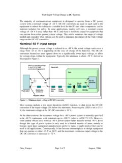
Nominal 48 V input range - psma.com
www.psma.comWide Input Voltage Range in DC Systems (Rev 3) Dave Cooper Page 3of 5 August, 2006 must vary over the 4:1 range, leading to very high peak currents and reduced efficiency.

Major Film Capacitor Dielectrics - psma.com
www.psma.comHCPP is high crystalline polypropylene Rough PP is polypropylene with a roughened surface PPS is polyphenylene sulfide This slide shows common films used as dielectrics in capacitors in the early part of the 21st century. It shows some of the common ... Segmented film …
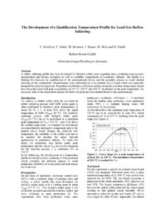
The Development of a Qualification Temperature Profile for ...
www.psma.comThe Development of a Qualification Temperature Profile for Lead-free Reflow Soldering V. Kirchner, C. Klein, M. Beintner, I. Brauer, R. Holz and H. Feufel ... To achieve a reliable solder joint the conventional reflow soldering process with SnPb solder paste is

POWER CONVERTER TOPOLOGY TRENDS - PSMA
www.psma.com8 “Mainstream” Converter Topologies Non-Isolated 1. Boost 4. 2. Buck-Boost 5. 3. Buck 6. Isolated Flyback Forward Push-Pull 7. Half Bridge 8. Full Bridge. Power levels numbers for general . discussion only. Exceptions aplenty.
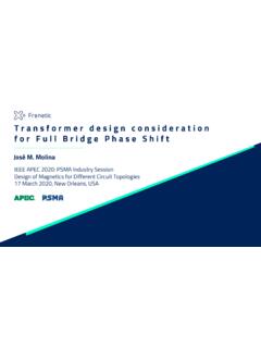
Transformerdesignconsideration forFull Bridge PhaseShift
www.psma.comMar 17, 2020 · produce an increment in the conduction losses in every component through a circulating current. For the magnetizing current, the effect is the same. The ideal design will have low magnetizing current, and the leakage inductance integrated in the operation for achieving ZVS without additional inductances. PAGE 19

Design Considerations for Power Supplies in High-Altitude ...
www.psma.comDesign Considerations for Power Supplies in High-Altitude Applications Kevin Parmenter, VP of Applications, USA, Excelsys Technologies. Altitude Environments in Power Applications Effects of Altitude on Power Electronics Regulatory …
IS97 EMI Conducted and Radiated Emissions - psma.com
www.psma.com(IEEE TRANSACTIONS ON POWER ELECTRONICS, VOL. 29, NO. 4, APRIL 2014 , Comparison and Reduction of Conducted EMI in SiC JFET and Si IGBT-Based Motor Drives Xun Gong, Member, IEEE, and Jan Abraham Ferreira, Fellow, IEEE) ADVANCED MATERIALS -THE KEY TO PROGRESS 15.01.2016 Seite 4
Related documents
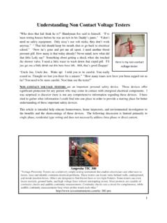
Understanding Non Contact Voltage Testers
www.homeinspect2020.comvoltage tester. Amprobe TIC 300 “Voltage Proximity Testers are a relatively simple testing instrument that enables electricians and other uses to locate, trace and identify common electrical problems. These testers can locate wires behind walls, underground, ... Continuity checks test a …

Photovoltaic System Commissioning and Testing
www.mavetech.net5.1 Continuity Testing 20 5.2 Polarity Testing 23 5.3 Voltage and Current Testing 24 5.3.1 Open-Circuit Voltage Testing 25 5.3.2 Short-Circuit Current Testing 25 5.4 Insulation Resistance Testing 26 5.5 System Functional Testing 29 5.5.1 Test Reports 30 6 System Performance Testing 30 6.1 Verifying Power and Energy Production 30
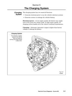
Section 5 The Charging System - Autoshop 101
www.autoshop101.com1. Keep the tester connections as for the alternator output test with no load. 2. Adjust engine speed to specified RPM (refer to the appropriate service manual). 3. Adjust the tester’s load control to obtain the highest ammeter reading possible while keeping the voltage reading at or above 12 volts. 4. Record the highest ammeter reading.
CHARGING SYSTEMS
www.autoshop101.comsuspected. Output current and voltage should meet the specifications of the alternator. If not, the alternator or regulator (IC or external) may require replacement. A Sun VAT-40 tester, similar testers, or a separate voltmeter and ammeter can be used. Toyota repair manuals detail the testing procedures with an ammeter and voltmeter.

TESTING FOR VOLTAGE DROP
drivcat.comcannot reliably be obtained through the use of continuity testing with an Ohmmeter. Multi-strand wires may test properly for continuity, but due to opens or corrosion in the line, display a substantial voltage drop when tested. Voltage Drop testing is a method of electrical diagnosis that can quickly locate high-resistance problems in a circuit.
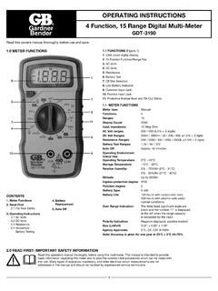
OPERATING INSTRUCTIONS 4 Function, 15 Range Digital …
file.ecmindustries.comWith DC voltage, the polarity of the test leads is a factor. ... Typical resistance/continuity measurements include resistors, potentiometer, switches, extension cords and fuses. ... Remove the screws in the back cover of the tester and carefully separate the back cover from the front. 3. Remove the battery from the contacts, noting the ...

WF-8900 Series
wfcoelectronics.comvoltage is changed back to 13.6 VDC for Absorption Mode. Lights that are powered from the output may change brightness slightly at that time. ... use a continuity tester to check for continuity. If the reverse polarity fuses are blown, it means the RV battery was accidentally connected in reverse, either at the battery or at the converter ...

ELECTRONIC PLAYGROUND TM - Elenco
www.elenco.comChanging Input Voltage 90 72. Non-inverting Dual Supply Op Amp 91 73. Inverting Dual Supply Op Amp 92 74. Non-inverting Amplifier 93 ... Audio Continuity Tester 143 122. Audio Rain Detector 144 123. Audio Metal Detector 145 124. Water Level Buzzer 146 ...
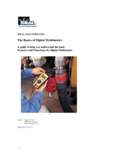
IDEAL INDUSTRIES INC.
www.idealind.comVoltage, current and resistance are the three most fundamental components of electricity. Voltage is measured in volts, current in amps and resistance in ohms. . Voltage, Current and Resistance Voltage is the pressure that is applied to a conductor. There are two common types of power sources, Alternating Current (AC) and Direct Current (DC).

ELECTRICIAN
www.rrbbnc.gov.involtage, current, resistance, power, power factor and energy using ammeter, voltmeter, ohm-meter, watt-meter, energy meter, power factor meter and phase sequence tester with proper care and safety. 12. Make choices to carry out basic jobs …