FLOWMETER INSTALLATION INSTRUCTIONS - …
FLOWMETER INSTALLATION INSTRUCTIONS - 1 - Rev 1, 4/25/2005 SAFETY FIRST: Follow ALL safety precautions when working on motor equipment-wear safety glasses! Fuel vapors and liquid are extremely flammable and explosive, personal injury and/or property damage could
Download FLOWMETER INSTALLATION INSTRUCTIONS - …

Information
Domain:
Source:
Link to this page:
Documents from same domain

NMEA 0183 GPS Receivers - Livorsi Marine
www.livorsi.comHIGHLIGHTS • 1Hz unit outputs NMEA0183 data at 4800 baud, 8 data bits, 1 stop bit, no parity (NMEA 0183 standard). • 10Hz unit outputs same
FUEL LEVEL SENDER - 3 TERMINAL WATER LEVEL …
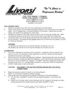
www.livorsi.comFUEL LEVEL SENDER - 3 TERMINAL WATER LEVEL SENDER - 3 TERMINAL Model # GSFLC All Lengths Model # GSWLC All Lengths Installation Instructions FUEL SENDING UNITS 1. Measure the depth of your tank from the outside top to the tank bottom.

THROTTLES AND CONTROLS - Livorsi Marine
www.livorsi.comTHROTTLES AND CONTROLS Model # TH SERIES (All Configurations) Installation Instructions Thank you for choosing Livorsi Marine® controls. Your new marine engine controls feature a 1 year

VESSELVIEW INSTALLATION INSTRUCTIONS
www.livorsi.comVESSELVIEW INSTALLATION INSTRUCTIONS 90-898278002 MAY 2008 Page 3 / 17 4. Remove the template and insert the VesselView into the panel to ensure fit.
Livorsi DTS Controls Single/Dual Engine Digital …
www.livorsi.comLivorsi DTS Controls- Single/Dual Engine Installation May 2016 Page 6 of 12 . Installing the Control to the Console . 1. Secure the control to the console using 4 x #10 screws and rubber O-Rings.

TEMPERATURE GAUGE and SENDER - Livorsi Marine
www.livorsi.comTemperature Gauge and Senders Trouble Shooting STEP ONE(this usually solves the problem) - Before you do anything else, check for defective wiring or grounds, as …

DIESEL TACHOMETER with SENDER - Livorsi Marine
www.livorsi.comDIESEL TACHOMETER with SENDER Models #GL4000MSGD All Colors ... Mechanical Take-off Rubber Washer Adaptor Sending Coupling Unit 2 of 2 1. Thread adaptor coupling onto sending unit and tighten. 2. Place rubber washer in large end of adaptor coupling. 3. Insert square end of drive tip into sending unit.

Installation and Operation Manual - livorsi.com
www.livorsi.comInstallation and . Operation Manual. ... operation manual provides users with a resource to realize the full potential and capabilities of Vantage View® instrumentation. Covered in this manual are display options, menu navigation and : menu function usage.

Installation and Operation Manual - Livorsi Marine
www.livorsi.comInstallation and Operation Manual ... instructions. FWA Warning Gauge Installation Vantage View® Installation Manual. g Installation Guide ... Installation Guide • Fuel Sender Compatibility Float Arm and Fuel/Water Level Senders are compatible with the Vantage View system. As well as 3

Parameter Range Analog Input LCD Display Name
www.livorsi.com75 Vantage View® Operation Manual ... Engine Oil Temperature 1 175 65262 0-500 ºF Eng Oil Temp Engine Total Hours of Operation 247 65253 0-999999 Hours Engine Hours Engine Speed 190 61444 0-10,000 RPM Engine Speed Engine Exhaust Gas Temperature 173 65270 0-3000 ºF Exh Gas Temp.
Related documents

Electromagnetic Flow Measuring System - aalto.ca
www.aalto.ca1 Safety instructions Proline Promag 50 8 Endress+Hauser 1.4 Return The following procedures must be carried out before a flowmeter requiring repair or calibration,

Electromagnetic Flow Measuring System - aalto.ca
www.aalto.caBA047D/06/en/03.05 50097083 Valid as of version: V 2.00.XX (Device software) Operating Instructions Proline Promag 53 Electromagnetic Flow Measuring System

Prowirl 72, Vortex Measuring System
www.controlswarehouse.com1 Safety instructions PROline Prowirl 72 8 Endress+Hauser 1.4 Return The following procedures must be carried out before a flowmeter requiring repair or

Technical Information VortexFlowMeasuringSystem …
www.controlswarehouse.comPlanning and Installation Orientation TheProwirl77cangenerallybe mountedinanypositioninthepiping. Anarrowshowingthedirectionofflowis markedonthemeterbody.

Installation and Flowmeter Orientation
www.emerson.com181 September 2014 Rosemount DP Flow www.rosemount.com Installation and Flowmeter Orientation Annubar installation considerations Table 1. Annubar Straight Run Requirements (1) Upstream (inlet) side

INSTALLATION, OPERATION AND MAINTENANCE
www.flo-gage.comINSTALLATION, OPERATION AND MAINTENANCE Threaded and Wafer Style Flowmeters Table of Contents Wafer Style Flowmeter Figure 1 Page 1. Principle of Operation««««««««« 2 2.