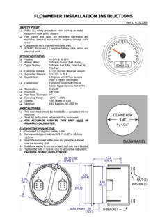
FLOWMETER INSTALLATION INSTRUCTIONS
FLOWMETER INSTALLATION INSTRUCTIONS - 4 - For the best possible operation, it is highly recommended that the sensor be installed between the fuel filter and the fuel pump inlet. There should be AT LEAST twelve inches of fuel hose (more is ok) between
Download FLOWMETER INSTALLATION INSTRUCTIONS

Information
Domain:
Source:
Link to this page:
Documents from same domain

NMEA 0183 GPS Receivers - Livorsi Marine
www.livorsi.comHIGHLIGHTS • 1Hz unit outputs NMEA0183 data at 4800 baud, 8 data bits, 1 stop bit, no parity (NMEA 0183 standard). • 10Hz unit outputs same
FUEL LEVEL SENDER - 3 TERMINAL WATER LEVEL …
www.livorsi.comFUEL LEVEL SENDER - 3 TERMINAL WATER LEVEL SENDER - 3 TERMINAL Model # GSFLC All Lengths Model # GSWLC All Lengths Installation Instructions FUEL SENDING UNITS 1. Measure the depth of your tank from the outside top to the tank bottom.

THROTTLES AND CONTROLS - Livorsi Marine
www.livorsi.comTHROTTLES AND CONTROLS Model # TH SERIES (All Configurations) Installation Instructions Thank you for choosing Livorsi Marine® controls. Your new marine engine controls feature a 1 year

VESSELVIEW INSTALLATION INSTRUCTIONS
www.livorsi.comVESSELVIEW INSTALLATION INSTRUCTIONS 90-898278002 MAY 2008 Page 3 / 17 4. Remove the template and insert the VesselView into the panel to ensure fit.
Livorsi DTS Controls Single/Dual Engine Digital …
www.livorsi.comLivorsi DTS Controls- Single/Dual Engine Installation May 2016 Page 6 of 12 . Installing the Control to the Console . 1. Secure the control to the console using 4 x #10 screws and rubber O-Rings.

TEMPERATURE GAUGE and SENDER - Livorsi Marine
www.livorsi.comTemperature Gauge and Senders Trouble Shooting STEP ONE(this usually solves the problem) - Before you do anything else, check for defective wiring or grounds, as …

DIESEL TACHOMETER with SENDER - Livorsi Marine
www.livorsi.comDIESEL TACHOMETER with SENDER Models #GL4000MSGD All Colors ... Mechanical Take-off Rubber Washer Adaptor Sending Coupling Unit 2 of 2 1. Thread adaptor coupling onto sending unit and tighten. 2. Place rubber washer in large end of adaptor coupling. 3. Insert square end of drive tip into sending unit.

Installation and Operation Manual - livorsi.com
www.livorsi.comInstallation and . Operation Manual. ... operation manual provides users with a resource to realize the full potential and capabilities of Vantage View® instrumentation. Covered in this manual are display options, menu navigation and : menu function usage.

Installation and Operation Manual - Livorsi Marine
www.livorsi.comInstallation and Operation Manual ... instructions. FWA Warning Gauge Installation Vantage View® Installation Manual. g Installation Guide ... Installation Guide • Fuel Sender Compatibility Float Arm and Fuel/Water Level Senders are compatible with the Vantage View system. As well as 3

Parameter Range Analog Input LCD Display Name
www.livorsi.com75 Vantage View® Operation Manual ... Engine Oil Temperature 1 175 65262 0-500 ºF Eng Oil Temp Engine Total Hours of Operation 247 65253 0-999999 Hours Engine Hours Engine Speed 190 61444 0-10,000 RPM Engine Speed Engine Exhaust Gas Temperature 173 65270 0-3000 ºF Exh Gas Temp.
Related documents
![Untitled-1 [cbperformance.net]](/cache/preview/e/5/f/7/b/1/6/5/thumb-e5f7b165dd01480669456e1777756b9f.jpg)
Untitled-1 [cbperformance.net]
cbperformance.netStandard Ground Gauge Light Light Switzh Rear of Gauges Light Sockets Terminals Floating Ground Gauge Light Socket Terminals Signal O BEGIN HERE

All American made boats use the ABYC(US) fuel sender.
mbcboats.comConnect multi connector end of harness to gauge’s Connect white wire on Speedometer to fuel tank sender wire (pink wire going to fuel sender).
Section EE-1 - TimberPro Inc
timberpro.comCummins QSC Engine - Installation and Parts Section EE-1 Cummins QSC Engine - Installation and Parts
Gauge Installation Instructions - DiscounteGauges.com
www.discountegauges.comCAUTION: Before drilling any holes into the tank, place the sender assembly on top of the tank to judge the proper hole placementŠone that will allow the float arm clearance inside the tank. SAFETY PRECAUTION: When making modifications to fuel tanks, it is essential that the tank be removed from the
FUEL LEVEL SENDER - 3 TERMINAL ... - Livorsi Marine, Inc.
www.livorsi.comFUEL LEVEL SENDER - 3 TERMINAL WATER LEVEL SENDER - 3 TERMINAL Model # GSFLC All Lengths Model # GSWLC All Lengths Installation Instructions FUEL SENDING UNITS 1. Measure the depth of your tank from the outside top to the tank bottom.

For Lever Arm Fuel Level Sender Siemens VDO Instruments
www.lofa.netFuel Level Sender Installation Instructions For Lever Arm Fuel Level Sender Part #0 515 010 169 Rev. 7/03 Allentown, Pennsylvania USA THE INSTRUCTIONS FOR INSTALLATION OF LEVER ARM FUEL LEVEL SENDER FOLLOW.
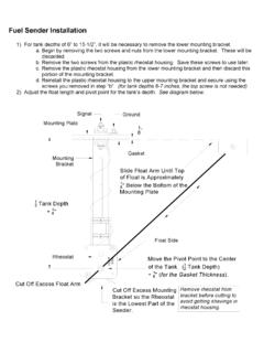
Fuel Sender Installation - Tanks Inc
www.tanksinc.comFuel Sender Installation 1) For tank depths of 6” to 15-1/2”, it will be necessary to remove the lower mounting bracket. a. Begin by removing the two screws and nuts from the lower mounting bracket.