
FT232R USB UART I.C. - SparkFun Electronics
This, in most cases, will remove the need to program the device EEPROM. Integrated USB Resistors - Previous generations of FTDI’s USB UART devices required two external series resistors on the USBDP and USBDM lines, and a 1.5 kΩ pull up resistor on USBDP. These three resistors have now been
Download FT232R USB UART I.C. - SparkFun Electronics

Information
Domain:
Source:
Link to this page:
Documents from same domain
AT Commands Reference Guide - SparkFun …
www.sparkfun.comAT Commands Reference Guide 80000ST10025a Rev. 0 - 04/08/06 Reproduction forbidden without Telit Communications S.p.A. written authorization - All …
DS1307 64 x 8 Serial Real-Time Clock
www.sparkfun.com1 of 12 100101 FEATURES Real-time clock (RTC) counts seconds, minutes, hours, date of the month, month, day of the week, and year with …

Advanced User Manual - SparkFun Electronics
www.sparkfun.comusage information and a summary of common commands refer to the Install Guide for a given product. Version 4.77 August 27, 2009 Roving Networks reserves the right to make corrections, modifications, and changes to its products, documentation and services ... Advanced User Manual.

Preliminary Product Specification v1 - SparkFun Electronics
www.sparkfun.comRevision 1.0 Page 3 of 75 nRF24L01+ Preliminary Product Specification Writing Conventions This product specification follows a set of typographic rules that make s the document consistent and easy

Single chip 2.4 GHz Transceiver nRF24L01
www.sparkfun.comPRELIMINARY PRODUCT SPECIFICATION nRF24L01 Single Chip 2.4 GHz Radio Transceiver Nordic Semiconductor ASA - Vestre Rosten 81, N-7075 Tiller, Norway - Phone +4772898900 - …
XBee /XBee-PRO RF Modules - SparkFun Electronics
www.sparkfun.comThe XBee®/XBee-PRO® RF Module was designed to mount into a receptacle (socket) and there-fore does not require any soldering when mounting it to a board. The XBee Development Kits con-tain RS-232 and USB interface boards which use two 20-pin receptacles to receive modules.

GSM/GPRS Module - SparkFun Electronics
www.sparkfun.comThis document gives an overview of the LinkSprite GSM/GPRS module: a miniature, single-side board, quad-band GSM 850/EGSM 900/DCS 1800/PCS 1900 module, ready for integration in various kinds of Fix wireless phones and other wireless devices.

16-Channel Constant-Current LED Driver
www.sparkfun.comA6282 Description The A6282 device is designed for LED display applications. This CMOS device includes an input shift register, accompanying data latches, and 16 MOS constant current sink drivers.

+3.3V Low Power Half-Duplex RS-485 Transceivers with ...
www.sparkfun.com10/15/02 SP3481/3485 Low Power Half-Duplex RS485 Transceivers © Copyright 2000 Sipex Corporation 2 SPECIFICATIONS T AMB = T MIN to T MAX and V CC = +3.3V ± 5% ...
XBee /XBee-PRO RF Modules - SparkFun Electronics
www.sparkfun.comDigi International Inc. 11001 Bren Road East Minnetonka, MN 55343 877 912-3444 or 952 912-3444 http://www.digi.com XBee®/XBee-PRO® RF Modules XBee®/XBee-PRO® RF ...
Related documents

PIC Assembly Language for the Complete Beginner
www.covingtoninnovations.com2 PART 2 - YOUR FIRST PROGRAM 2.1 Assembly language APICspendsitstime readinginstructions from theprogram memory, one after another, and doing whatever these instructions say. Each instruction consists of 14 bits. If you could see the bits as binary ones and zeroes, the program in Figure 5 would look like this: 11000000000000 00000001100110 ...

AP Physics 1 and 2 Exam Questions - College Board
secure-media.collegeboard.orga single battery and resistors in series and in, at most, one parallel branch and predict how those values would change if configurations of the circuit are changed. [See Science Practices 6.4 and 7.2] 3. A person driving a car suddenly applies the brakes. The car takes 4 s to come to rest while traveling 20 m at constant acceleration.

Offshore Substation Design Development of Standards
www.boem.govDraft May 29, 2015 Sean Jessup, PE Dan Dolan, PE Final July 20, 2015 Sean Jessup, PE Dan Dolan, PE

Learning Arduino with C Programming
c-stem.ucdavis.edu9 Using Photo-Resistors to Change the Brightness and Color of an RGB LED 68 ... would be such that the code from a Ch program can be copied and paste into the Arduino programming environment and function the same way, creating a smooth transition from ChIDE to …
Temperature Measurement with a Thermistor and an …
web.cecs.pdx.eduThe voltage divider has two resistors in series. In the left side of Figure 1, the upper resistor is the thermistor, with variable resistance R t. The lower resistor has a xed resistance R. A voltage V s is applied to the top of the circuit2. The output voltage of the voltage divider is V o, and it depends on V s and R, which are known, and R
8-bit Microcontroller with 2K Bytes In-System Programmable ...
ww1.microchip.comOct 19, 2010 · resistors are activated. The Port B pins are tri-stated when a reset condition becomes active, even if the clock is not running. Port B also serves the functions of various special features of the ATtiny2313 as listed on page 53. Port D (PD6..PD0) Port D is a 7-bit bi-directional I/O port with internal pull-up resistors (selected for each bit). The

ATmega16U4/ATmega32U4 - Microchip Technology
ww1.microchip.comincluding: C compilers, macro assemblers, program debugger/simulators, in-circuit emulators, and evaluation kits. 2.2 Pin Descriptions 2.2.1 VCC Digital supply voltage. 2.2.2 GND Ground. 2.2.3 Port B (PB7..PB0) Port B is an 8-bit bi-directional I/O port with internal pull-up resistors (selected for each bit). The Port B output

Resistor Color Code Chart - TeachEngineering
www.teachengineering.orgResistors are devices that limit current flow and provide a voltage drop in electrical circuits. Because carbon resistors are physically small, they are color-coded to identify their resistance value in ohms. The use of color bands on the body of a resistor is the most common system for indicating the value of a resistor.
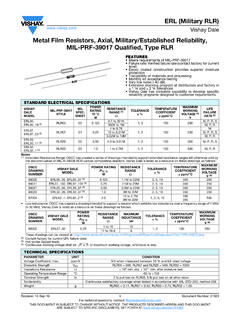
Metal Film Resistors, Axial, Military / Established ...
www.vishay.comMetal Film Resistors, Axial, Military / Established Reliability, MIL-PRF-39017 Qualified, Type RLR FEATURES • Meets requirements of MIL-PRF-39017 • Failure rate: Verified failure rate (conta ct factory for current level) • Epoxy coated construction provides superior moisture protection • Traceability of materials and processing

Using SPI Flash with 7 Series FPGAs Application Note - Xilinx
www.xilinx.comPROGRAM_B Input Dedicated Active-Low asynchronous full-chip reset. PUDC_B Input Dual-Purpose Controls I/O (except bank 0 dedicated I/Os) pull-up resistors during configuration. This pin must be externally terminated. 0 = Pull-up resistors during configuration 1 = 3-state output during configuration EMCCLK Input Dual-Purpose