
Installation Manual
This equipment meets Underwriters Laboratory Standard 325 (UL 325). However, gate equipment has hazards associated with its use and therefore by installing this product the installer and user accept full responsibility for following and noting the installation and safety instructions. Failure to follow
Download Installation Manual

Information
Domain:
Source:
Link to this page:
Documents from same domain

Installation Manual - Mighty Mule
www.mightymule.comfull responsibility for following and noting the installation and safety instructions. Failure to follow ... You must read the installation manual for detailed

MM571W MM572W
www.mightymule.comThis equipment meets Underwriters Laboratory Standard 325 (UL 325). However, gate equipment has hazards associated with its use and therefore by installing this product the installer and user accept full responsibility for following and noting the installation and safety instructions. Failure to follow

Wir - Mighty Mule
www.mightymule.comPrior to any assembly of the MMS100, ensure that the Mighty Mule gate operator is turned OFF and disconnected from its power source. If required, punch out the access hole for the Auxiliary Antenna. Align the connectors, then plug in the small …

25 Code GTO Digital Keypad - Mighty Mule
www.mightymule.comStep 7: Slide the keypad into the cover and secure with the small screws provided. (FIG. 8) OUT COM Hard-wire from Gate Opener #1 #2 1 2 ABC 3 DEF 4 GHI 5 JKL 6 MNO 7 PRS 8 TUV 9 WXY 0 Connect #1 wire from the OUT terminal on the keypad to the CYCLE terminal on the opener control board. Connect #2 wire from the COM terminal on the keypad to COM ...

FM500 Installation Manual - Mighty Mule
www.mightymule.commanual cannot be completely exhaustive in nature. They do, however, provide an overview of the safe design, installation, and use of this product. CAREFULLY READ AND FOLLOW ALL SAFETY PRECAUTIONS, ARNINGS, W AND INSTALLATION INSTRUCTIONS TO ENSURE THE SAFE SYSTEM DESIGN, INSTALLATION, AND USE OF THIS PRODUCT.
Installation Manual - Mighty Mule Automatic Gate Openers ...
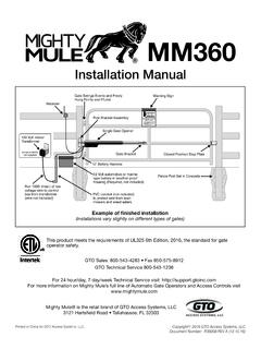
www.mightymule.comii Mighty Mule MM360 Installation Instructions Product Usage The Mighty Mule Gate Operator meets all of the safety requirements of a Class I Residential Vehicular Gate Operator and is intended for use solely with vehicular swing gates in single-family residential applications that meet the Class I category listed

Vehicle Detection Alarm - Mighty Mule
www.mightymule.comTurn dial counter-clockwise to INCREASE audio volume. RECEIVER TOP VIEW. 4 Installing Transmitter Batteries ... This equipment has been tested and found to comply with the limits for a Class B digital device, pursuant to Part 15 of the ... generates, uses and can radiate radio frequency energy and, if not installed and used in accordance with ...

Instructions for Gate Opener Single Button Entry Transmitter
www.mightymule.comInstructions for Gate Opener Single Button Entry Transmitter FCC Regulation: This device complies with Part 15 of the FCC Rules. Operation is subject to the following two conditions: (1) This device may not cause harmful interference, and (2) This device must accept any interference received, including interference that may cause undesired ...

MM371W MM372W
www.mightymule.com12 Volt automotive or marine type battery in weather proof housing (not included). Example of Dual Gate finished installation (Installations vary slightly on different types of gates) MM371W MM372W Single gate installation [MM371W] Dual gate installation [MM372W] This product meets the requirements of UL325, the standard for gate operator safety.

AUTOMATIC GATE LOCK - Mighty Mule
www.mightymule.comRemember to check the alignment and mark positions before drilling holes in fence post . Illustration F Clevis Pin Receiver Locking Cap GTO Automatic Gate Lock Carriage bolts, washers, and nuts (not provided; size of fasteners depends on the gate) Remember to check the alignment and mark positions before drilling holes in fence post and gate ...
Related documents
Owner's Manual and Installation Instructions
c.searspartsdirect.commatch a 3-wire receptacle of NEMA Type 10-30R. If connecting by direct wire: Power supply cable must match power supply (4-wire or 3-wire) and be: • Flexible armored or non-metallic sheathed copper cable (with ground wire). All current-carrying wires must be insulated. • 10 gauge solid copper wire (Do not use aluminum.) dryer.

A GUIDE TO INSULATED HVAC DUCT SYSTEMS
insulationinstitute.orgwire-reinforced inner air conduit is wrapped with resilient fibrous glass and jacketed with a flexible vapor retarder of reinforced foil or plastic film. These flexible products can conform to bends when connecting trunk ducts to diffusers, or when routing ductwork through obstructed areas. (NAIMA members do not manufacture flexible
MOSLEY Trap Master Version MODEL TA-33-M 2011
www.radiomanual.infoIn building the antenna we have removed the majority of the burrs, however, due to the number of pieces of tubing, the cost of labor, the time consumption; some pieces may still have a few remaining burrs. Double-check the pieces before trying to put them together! The tubing Mosley uses is made for us and the telescoping tolerances are very close.

MICROWAVE HOOD COMBINATION INSTALLATION …
images.thdstatic.comIf installing the microwave oven near a left sidewall, make sure there is at least 6" (15.2 cm) of clearance between the wall and the microwave oven so that the door can open fully. Some cabinet and building materials are not designed to withstand the heat produced by the microwave oven for cooking.
MM571W MM572W
www.mightymule.comThis equipment meets Underwriters Laboratory Standard 325 (UL 325). However, gate equipment has hazards associated with its use and therefore by installing this product the installer and user accept full responsibility for following and noting the installation and safety instructions. Failure to follow

NEMA Standards Publication VE 2-2006 - Cable tray
www.mphusky.comSections. Section approval of the standard does not necessarily imply that all section members voted for its approval or participated in its development. At the time it was approved, the Metal Cable Tray and Nonmetallic Cable Tray Sections were composed of the following members: Allied Tube & Conduit/Cope—Harvey, IL Cablofil Inc—Mascoutah, IL
METER LOOP SPECIFICATIONS FOR SINGLE PHASE SERVICE
www.samhouston.netgrade) or by installing it in ½-inch thin wall EMT conduit securely attached to the building or pole. 3. SERVICE DISCONNECTS shall be manually operable and shall have over current protection (either fuses or circuit breakers) rated not to exceed the ampacity of the service entrance conductors and shall be UL listed for use as service equipment.

USG Exterior Ceiling Systems SYSTEMS GUIDE
www.usg.com• Aluminum panels provide a monolithic appearance. • Easy Installation into standard USG Donn Brand Fineline "DXFEVH" Acoustical Suspension System. • Available panel sizes: 2' x 2', 2' x 4', 2' x 6', 2' x 8', 4' X 4', 30" X 30" & 30" X 60". • Downward panel access is …

MICROWAVE HOOD COMBINATION INSTALLATION …
www.whirlpool.comIf installing the microwave oven near a left sidewall, make sure there is at least 6" (15.2 cm) of clearance between the wall and the microwave oven, so that the door can open fully. Some cabinet and building materials are not designed to withstand the heat produced by the microwave oven for cooking.

OPERATION, SERVICE & PARTS MANUAL
www.yalehoist.comor mounting to an overhead suspension (standard model), is located on the top of the frame. An aluminum alloy gearcase, attached to one end of the hoist frame, houses a two-reduction gear train and a mechanical load brake. A gearcase cover and a brake cover, both of aluminum alloy, mounted on the end of the gearcase, houses an automatic motor ...