KB-TZ2 TECHNICAL GUIDE - Hilti
Allowable stress design information The load tables in this section were developed for use in NQA projects utilizing allowable stress anchorage design when appropriate per their design basis. The load values were developed based on testing per ACI 355.2 and ASTM E488. Additional information,
Download KB-TZ2 TECHNICAL GUIDE - Hilti

Information
Domain:
Source:
Link to this page:
Documents from same domain

Page 1/8 Safety Data Sheet acc. to ISO 11014 - Hilti USA
www.hilti.comPage 2/8 Safety Data Sheet acc. to ISO 11014 Printing date 05/19/2015 Version number 5 Reviewed on 05/19/2015 (Contd. of page 1) 40.2.7 H319 Causes serious eye irritation.
Hilti. Outperform. Outlast.
www.hilti.comSelector Guide Through-Penetration Joint Reference Data Firestop Mortar (CP 637) Product description ... Concrete and masonry assemblies Expansion on setting (approx.)Walls and floors rated up to 4 hours ... Mix ratio (recommended, mortar to water):

ICC-ES Evaluation Report ESR-2269 - Hilti
www.hilti.com1.0 EVALUATION SCOPE Compliance with the following codes: 2018, 2015, and 2012 International Building Code ® (IBC) 2018, 2015, and 2012 International Residential Code® (IRC) For evaluation for compliance with codes adopted by the Los Angeles Department of Building and Safety (LADBS), see ESR-2269 LABC and LARC Supplement.

HILTI TECHNICAL BULLETIN
www.hilti.comMar 04, 2018 · )n ≤ 1, where n=5/3 for 3/8- and 1/2-inch diameters (No. 3 and No. 4 rebar) and n=1 for 5/8 and 3/4-inch diameter or No. 5 and No. 6 rebar. 9 The critical spacing, s cr, is the smallest anchor spacing where full load values may be used. The minimum spacing, s min, is the minimum anchor spacing for which values are

HIT-RE 500 V3 - Hilti
www.hilti.comSafety information for 2-Component-products 18/06/2020 US-OSHA - en 2/27 IF IN EYES: Rinse cautiously with water for several minutes. Remove contact lenses, if present and easy to do. Continue rinsing. If skin irritation or rash occurs: Get medical advice/attention. If eye irritation persists: Get medical advice/attention.

Hilti HIT-HY 200 with HIT-V
www.hilti.comAnchor rods HIT-V GR / -HCR) are available in variable length MIO M12 TE 16 M16 M20 M24 TE 40 M27 - TE 70 M30 compressed air gun or blow out pump, set of cleaning brushes, dispenser Drill hole to the required embedment depth with an appropriately sized Hilti TE-CD Or TE-YD hollow drill bit with Hilti vacuum attachment. This drilling
Hilti HIT-HY 200 with rebar
www.hilti.comHilti HIT-HY 200 with rebar Benefits - suitable for cracked and non- cracked concrete C 20/25 to C 50/60. - Approved automatic cleaning with the use of the hollow drill-bit high loading capacity, excellent handling HY 200-R version with extended curing time for rebar applications small edge distance and anchor spacing possible

OPENINGS IN COMPOSITE FLOOR DECKS - Hilti
www.hilti.comin-situ reinforced concrete topping. The decking not only acts as a permanent formwork to the concrete, but also provides sufficient shear bond with the concrete so that, when the concrete has cured, the two materials act together compositely to resist the loads on the deck. Openings in floor decks are a common part of any building.

HIT-1 ADHESIVE ANCHORING SYSTEM - Hilti
www.hilti.comHIT-1 ADHESIVE ANCHORING SYSTEM Technical Supplement PRODUCT DESCRIPTION Hilti HIT-1 is a hybrid adhesive mortar combining resin, hardener, cement, and water. It’s formulated for fast curing and easy installation in a wide range of concrete and masonry base materials with temperatures ranging from 32°F (0°C) up to 95°F (35°C).

ICC-ES Evaluation Report ESR-4266
www.hilti.comDesign strength of anchors complying with the 2012 IBC as well as Section R301.1.3 of the 2012 IRC, must be determined in accordance with ACI 318-11 Appendix D and this report. Design parameters provided in Table 4, Table 5, Table 6 and Table 7 of this report are based on the 2021 IBC (ACI 318-19), 2018 and 2015 IBC (ACI 318-14) and the 2012 IBC
Related documents

Basic Pipe Stress Analysis Tutorial - sstusa.com
www.sstusa.comStep 1. Review the thermal stress contour plot first. The plot is color-coded such that “blue” region denotes areas with the least stress ratios (where stress ratio equals to actual computed stress divided by material allowable stress), “green” region …
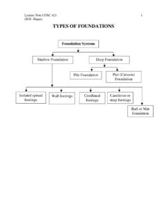
TYPES OF FOUNDATIONS
people.tamu.edutensile stress results at the left side. For p max less than allowable soil bearing capacity, no uplift is expected at the left end of the footing, and the center of gravity of the triangular bearing stress distribution coincides with the point of action of load, P. Downward Load = Area of upward triangular stress block x width P = ½ (p max) (3X)W

Structural Steel Design - Free
freeit.free.fr50 70-100 To 1.5 stress for A529 steel allows for savings in weight. A529 supersedes A441. A572 Grade 42 42 60 To 6 Similar to A441. Grades 60 and 65 Grade 50 50 65 To 4 not suitable for welded bridges. Grade 60 60 75 To 1.25 Grade 65 65 80 To 1.25 A242 42 63 1.5 to 5 Riveted, bolted, and 46 67 0.75 to 1.5 welded buildings and bridges.
115 - Food and Agriculture Organization
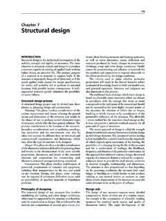
www.fao.orgChapter 7 – Structural design 117 The allowable stress in the rope is = 7.5 Therefore: Thus: 60° 30° A B P=5kN T 2 T 1 P Free body diagram T 2 = 2.5 kN T= 4.3 kN

2. Design of Welded Connections 2.1 Stresses
app.aws.orgapplicable design specifications. 2.1.2 Allowable Increase. Where the applicable design specifications permit the use of increased stresses in the base metal for any reason, a corresponding increase shall be applied to the allowable stresses given herein, but not to the stress ranges permitted for base-metal or weld metal subject to cyclic loading.

Wood Handbook--Chapter 6--Lumber Stress Grades and …
www.fpl.fs.fed.us5-min bending stress (AF&PA 1996), or (b) the allowable stress design (ASD), which is based on a design stress at the lower 5th percentile 10-year bending stress. The properties depend on the particular sorting criteria and on additional factors that are independent of the sorting criteria. Design properties are lower than the average ...

Structural Analysis by Hand - VBCOA
vbcoa.orgAllowable shear stress, F’v The maximum shear stress permissible for a specified structural member Units for stress: pounds per square inch lbs/in2 psi 47 Step 6A: Determine F’v (psi) Allowable shear stress “Raw” stress based on wood …
Masonry Design - Texas A&M University
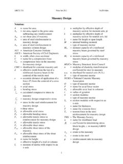
faculty-legacy.arch.tamu.eduARCH 331 Note Set 28.1 Su2014abn 2 Reinforced Masonry Design Structural design standards for reinforced masonry are established by the Masonry Standards Joint Committee consisting of ACI, ASCE and The Masonry Society (TMS), and presents allowable stress design as well as limit state (strength) design.
Introduction to Railroad Track Structural Design
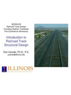
web.engr.uky.edu- Company design standards will dictate (e.g. Army allows a design unconfined compressive strength (q u) of 1.0 q u for "normal" traffic levels - less than 5 MGT/yr - and design of 0.8 q u when traffic levels exceed 5 MGT.) - Hay recommends factor of safety of 1.5 as applied to an ultimate bearing capacity of < 2.5 q u, thus allowable stress ...
Micropiles Design 101 - Structural Engineers
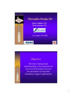
www.sefindia.orgG allowable b D P FS L × × × = − α π AASHTO LRFD Design Table 10.5.5.2.4-1 - Resistance Factors for Geotechnical Resistance of Axially Loaded Micropiles METHOD/SOIL/CONDITION RESISTANCE FACTOR Compression Resistance of Single Micropile, φ stat Side Resistance (Bond Resistance): Presumptive Values 0.55(1) Tip Resistance on Rock O’Neill ...